
Specifications

S7-200 Programmable Controller System Manual
460
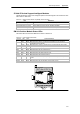
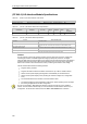
(CP 243--2) AS--Interface Module Specifications
Table A-62 (CP 243--2) AS-Interface Module Order Number
Order Number Expansion Model EM Inputs EM Outputs Removable Connector
6GK7 243--2AX01--0XA0 (CP 243--2) A S--Interface Module 8 Digital and 8 Analog 8 Digital and8 A nalog Yes
Table A-63 (CP 243--2) AS-Interface Module General Specifications
Order Number
Module Name and
Description
Dimensions (mm)
(W x H x D)
Weight Dissipation
VDC Requirements
+5 VDC From
AS--Interface
6GK7 243--2AX01--0XA0 (CP 243--2) AS--Interface
Module
71 x 80 x 62 approx.
250 g
3.7 W 220 mA 100 mA
Table A-64 (CP 243--2) AS-Interface Module Specifications
General 6GK7 243--2AX01--0XA0
Cycle time 5mswith31slaves
10 ms wi th 62 A S--I slaves using the extended addressi ng mode
Configuration Set button on the front panel, or us e the total configuration command (refer to the
descripti on of the AS-- I commands in the CP 243--2 AS--I Interface Master manual)
AS--I master profiles supported M1e
Attachment to the AS--I cable Via an S7-200 terminal block. Permitted current loading from terminal 1 to 3 or from
terminal2to4maximum3A.
Address range One digital module with 8 digital inputs and 8 digital outputs, and
One anal og module with 8 analog inputs and 8 analog outputs
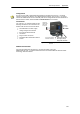
Features
You c an operate up to two AS--Interface modules on the S7-200 at the same time, significantly
increasing the number of available digital and analog inputs/outputs (maximum 124 digital
input/124 digital output on AS--Interface per CP). Setup times are reduced because of the ability to
configure at the touch of a button. LEDs reduce downtime in the event of an error by displaying
status of the CP and of all connected slaves, and by monitoring AS--Interface main voltage.
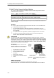
The AS--Interface Module has the following features:
- Supports analog modules
- Supports all master functions and allows connections for up to 62 AS--Interface slaves
- LEDs in the front plate display operating status and availability of connected slaves.
- LEDs in the front plate display errors (including AS--Interface voltage error, configuration
error)
- Two terminals allow direct connection of the AS--Interface cable.
- Two buttons display the status information of the slaves, switch operating mode, and adopt
the existing configuration as the SET configuration.
You can use the STEP 7--Micro/WIN AS-i Wizard to configure the (CP 243--2) AS --Interface
module. The AS--Interface Wizard helps you use the data from an AS-Interface network in your
configuration. To start the AS--i Wizard, select the Tools > AS--i Wizard menu command.
AS-i