
Specifications
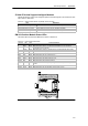

S7-200 Programmable Controller System Manual
452
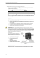
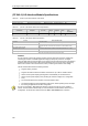
Wiring Diagrams
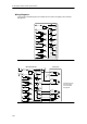
In the following schematic figures, the terminals are not in order. See Figure A-34 for terminal
arrangement.
P/S 3.3K
3.3K
3.3K
T1
P0
P1
3.3K
DIS
CLR
L+
M
M
P0--
P0+
P1--
P1+
M
STOP
5.6K
1M
1K
RPS
5.6K
2M
1K
ZP
3M
LMT+
5.6K
1K
LMT--
5.6K
4M
1K
+5VDC
Figure A-35 Internal Schematic for the Inputs and Outputs of the EM 253 Position Module
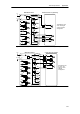
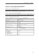
P/S 3.3K
3.3K
3.3K
T1
P0
P1
3.3K
DIS
CLR
L+
M
M
P0--
P0+
P1--
P1+
M
STOP
1M
RPS
2M
ZP
3M
LMT+
LMT--
5.6K
4M
1K
+5VDC
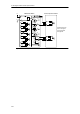
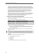
EM253 Motion Module FM Step Drive
DIR
DIR_N
PULSE
PULSE_N
GATE_N
GND
GND
GND
24V_RTN
ENABLE
ENABLE_N
+24V+24V
24V_RTN
Terminals are not in
order . See Figure
A-34 for terminal
arrangement.
Figure A-36 Connecting an EM 253 Position Module to a SIMATIC FM Step Drive