
Specifications

S7-200 Programmable Controller System Manual
450
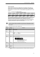
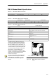
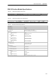
Table A-51 EM 253 Position Module Specifications, continued
6ES7 253 --1AA22--0XA0General
Output Features
Number of integrated outputs
Output type
P0+, P0--, P1+, P1--
P0, P1, DIS, CLR
6 points (4 signals)
RS422/485 driver
Open drain
Output voltage
P0, P1, RS--422 drivers, differential output voltage
Open circuit
Into optocoupl er diode with 200Ω series resistance
100Ω load
54Ω load
P0, P1, DIS, CLR open drain
recommended voltage, open circuit
permissi ble vol tage, open circuit
Sink current
On state resis tance
Off state leakage current, 30 V DC
Internal Pull up resistor, output drain to T1
3.5 V typical
2.8 V minimum
1.5 V minimum
1.0 V minimum
5 VDC, avai lable from module
30 VDC
1
50 mA maximum
15Ω maximum
10 µA maxi m um
3.3K Ω
2
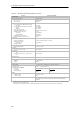
Output current
Number of output groups
Outputs on si m ultaneously
Leakage current per point
P0, P1, DIS, CLR
Overload Protection
1
All at 55° C (horizontal), A ll at 45° C(vertical)
10 µA maxi m um
No
Isolation (field to logic)
Optical Isolation (Galvanic) 500 VAC for 1 mi nute
Output del ay
DIS, CLR: Off to On / On to Off 30 µs, maximum
Pulse distortion
P0, P1, outputs, RS--422 drivers, 100 Ω external
load
P0, P1 outputs, open drain, 5 V / 470 Ω external
load
75 ns maximum
300 ns maximum
Switchi ng frequency
P0+, P0--, P1+, P1--, P0 and P1 200 kHz
Cable length
Unshielded
Shielded
Not recommended
10 meters
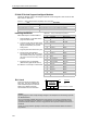
Power Supply
L+ supply v oltage
Logic supply output
L
l
t
5
V
D
C
l
d
11 to 30 V DC (Clas s 2, Limited Power, or sensor power from P LC)
+5 VDC +/-- 10%, 200 mA maximum
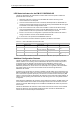
L+ supply c urrent vs. 5 VDC l oad
Load current
0 mA (no load)
200 mA (rated load)
12 VDC Input
120 mA
300 mA
24 VDC Input
70 mA
130 mA
Isolation
L+ power to logi c
L+ power to inputs
L+ power to outputs
500 VAC for 1 m inute
500 VAC for 1 m inute
None
Reverse Polarity L+ input and + 5V output are diode-protected. P lacing a positiv e voltage on any M
terminal with respect to output point connec tions c an result in potenti ally damaging
current flow.
1
Operation of open drain outputs above 5 VDC m ay increase radio frequency emissions abov e permissible limits. Radio frequency c ontainment measures
may be required for your system or wiring.
2
Depending on y our pul se receiver and cable, an addi tional ex ternal pull up resistor may i mprove pulse signal qual ity and noise i mmunity.