
Specifications

Technical Specifications Appendix A
449
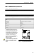
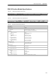
EM 253 Position Module Specifications
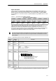
Table A-49 EM 253 Position Module Order Number
Order Number Expansion Model EM Inputs EM Outputs Removable Connector
6ES7 253 --1AA22 --0XA0 EM 253 P osition Module -- 8
1
Yes
1
Eight Q outputs are used as logical controls of the motion function and do not directly control any external signals.
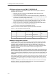
Table A-50 EM 253 Position Module General Specifications
Order Number
Module Name and
Description
Dimensions (mm)
(WxHxD)
Weight Dissipation
VDC Requirements
+5 VDC +24 VDC
6ES7 253 --1AA22 --0XA0 EM 253 Position Module 71.2 x 80 x 62 0.190 kg 2.5 W 190 mA See below
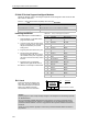
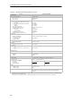
Table A-51 EM 253 Position Module Specifications
General 6ES 7 253--1AA22--0XA0
Input Features
Number of inputs 5 points
Input type
All except ZP
ZP
Sink/Source (IEC Type 1 sink, except ZP)
Sink only, current li miting for wide voltage range
Input Voltage
Maximum Continuous permissible
STP, RPS, LMT+, LMT--
ZP
Surge (all inputs)
Rated Value
STP, RPS, LMT+, LMT--
ZP
Logic “1” si gnal (minimum)
STP, RPS, LMT+, LMT--
ZP
Logic “0” si gnal (maximum)
STP, RPS, LMT+, LMT--
ZP
30 VDC
30 VDC at 20 mA, maximum
35 VDC for 0.5 sec.
24 VDC at 4 mA, nominal
24 VDC at 15 mA, nominal
15VDCat2.5mA,minimum
3 VDC at 8.0 mA, minimum
5VDCat1mA,maximum
1VDCat1mA,maximum
Isolation (field to logic)
Optical Isolation (Galvanic)
Isolati on groups of
500 VAC for 1 m inute
1 point for STP, RPS, and ZP
2 points for LMT+ and LMT--
Input Delay Ti mes
STP, RPS, LMT+, LMT--
ZP (countable pulse width)
0.2 ms to 12.8 ms, user selectable
2 µsec minimum
Connection of 2 Wire Proximity Sensor (Bero)
Permissible l eakage current
1 mA, maximum
Cable Length
Unshielded
STP, RPS, LMT+, LMT--
ZP
Shielded
STP, RPS, LMT+, LMT--
ZP
30 meters
Not recommended
100 meters
10 meters
Number of inputs on simultaneously All at 55° C (horizontal), All at 45° C(vertical)