
Specifications

Technical Specifications Appendix A
447
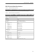
EM 241 Modem Module Specifications
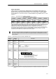
Table A-44 EM 241 Modem Module Order Number
Order Number Expansion Model EM Inputs EM Outputs Removable Connector
6ES7 241 --1AA22 --0XA0 EM 241 Modem Module -- 8
1
No
1 Eight Q outputs are used as logical controls of the modem function and do not directly c ontrol any external signals.
Table A-45 EM 241 Modem Module General Specifications
Order Number
Module Name and
Description
Dimensions (mm)
(WxHxD)
Weight Dissipation
VDC Requirements
+5 VDC +24 VDC
6ES7 241 --1AA22 --0XA0 EM 241 Modem Module 71.2 x 80 x 62 190 g 2.1 W 80 mA 70 mA
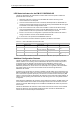
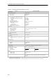
Table A-46 EM 241 Modem Module Specifications
General 6ES7 241--1AA22--0XA0
Telephone Connection
Isolation
(phone line to logic and fi eld power) 1500 VAC (Galvanic)
Phys ical connection RJ11 (6 position, 4 wire)
Modem standards Bell 103, Bell 212, V.21, V.22, V.22 bis, V.23c, V.32, V.32 bis,
V.34 (default)
Security features Password
Callback
Dialing Pulse or Tone
Messagi ng Protocols Numeric
TAP (alphanumeric)
UCP commands 1, 30, 51
Industrial Protocols Modbus
PPI
24 VDC Input Power Requirements
Voltage range
Isolation (field power to logic)
20.4 to 28.8 VDC
500 VAC for 1 minute
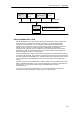
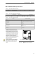
The EM 241 Modem Module replaces the
function of an external modem connected to
the c ommunications port of the CPU. With an
EM 241 installed in your S7-200 system, all
you need to communicate with your CPU from
a remote location is a personal computer with
an external modem and STEP 7--Micro/WIN.
See Chapter 7, Communicating over a
Network, for information on configuring. See
Chapter 10, Creating a Program for the Modem
Module for programming and advanced
features of the module.
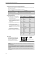
You can use the STEP 7--Micro/WIN Modem
Expansion Wizard to configure an EM 241
Modem Module. See Chapter 10 for more
information about the Modem Expansion
Country Code Switch
i
n
f
o
r
m
a
t
i
o
n
a
b
o
u
t
t
h
e
M
o
d
e
m
E
x
p
a
n
s
i
o
n
Wizard.
Figure A-32 EM 241 Modem Module Terminal Block
Diagram
Modem
Expansion