
Specifications

S7-200 Programmable Controller System Manual
436
S7 -200 CPUs that Support Intelligent Modules
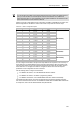
The EM 277 PROFIBUS--DP slave module is an intelligent expansion module designed to work
with the S7-200 CPUs shown in Table A-39.
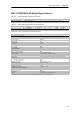
Table A-39 EM 277 PROFIBUS--DP Module Compatibility with S7-200 CPUs
CPU Description
CPU 222 Rel. 1.10 or greater CPU 222 DC/DC/DC and CPU 222 AC/DC/Relay
CPU 224 Rel. 1.10 or greater CPU 224 DC/DC/DC and CPU 224 AC/DC/Relay
CPU 224XP Rel. 2.0 or greater CPU 224XP DC/DC/DC and CPU 224XP AC/DC/Relay
CPU 226 Rel. 1.00 or greater CPU 226 DC/DC/DC and CPU 226 AC/DC/Relay
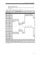
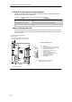
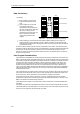
Address Switches and L EDs
The address switc hes and status LEDs are located on the front of the module as shown in Figure
A-26. The pin-out for the DP slave port connector is also shown. See Table A-43 for a description
of the status LEDs.
Address Switches:
x10=sets the most significant digit of the address
x1= sets the least significant digit of the address
DP Slave Port Connector
Front View of EM 277 PROFIBUS--DP
9-Pin Sub D Connector Pin-out
5
1
9
6
9-pin D
Female
Connector
Pin # Description
1 Chassis ground, tied to the connector shell
2 24V Return (same as M on terminal block)
3 Isolated Signal B (RxD/TxD+)
4 Isolated Request to Send (TTL level)
5 Isolated +5V Return
6 Isolated +5V (90 mA maximum)
7 +24V (120 mA maximum, with reverse
voltage protection diode)
8 Isolated Signal A (RxD/TxD--)
9 No Connection
Note: Isolated means 500V of isolation from
digital logic and 24V input power.
Figure A-26 EM 277 PROFIBUS--DP