
Specifications

S7-200 Programmable Controller System Manual
394
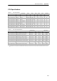
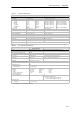
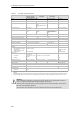
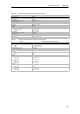
Table A-1 Technical Specifications, continued
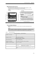
Electromagnetic Compatibility — Immunity per EN61000--6--2
1
EN 61000--4--2 Electrostatic discharge 8 kV air discharge to all surfaces and communications port,
4 kV contact discharge to exposed conductive surfaces
EN 61000--4--3 Radiated electromagnetic field 10 V/m, 80--1000 MHz, 1.4--2.0 GHz and 2.0--2.7 GHz, 80% AM at 1kHz
EN 61000--4--4 Fast transient bursts 2 kV, 5 kHz with coupling network to AC and DC system power
2 kV, 5 kHz with coupling clamp to I/O
1 kV, 5 kHz with coupling clamp to communications
EN 61000--4--5 Surge immunity Power supply: 2 kV asymmetrical, 1 kV symmetrical
I/O 1 kV symmetrical
(24 VDC circuits require external surge protection)
EN 61000--4--6 Conducted disturbances 0.15 to 80 MHz, 10 V RMS, 80% AM at 1kHz
EN 61000--4--11 Voltage dips, short
interruptions and voltage variations
>95% reduction for 8.3 ms, 83 ms, 833 ms, and 4167 ms
VDE 0160 Non-periodic overvoltage At 85 VAC line, 90° phase angle, apply 390 V peak, 1.3 ms pulse
At 180 VAC line, 90° phase angle, apply 750 V peak, 1.3 ms pulse
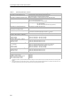
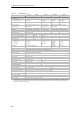
Electromagnetic Compatibility — Conducted and Radiated Emissions per EN 61000--6--3
2
and EN 61000--6--4
EN 55011, Class A, Group 1, conducted
1
0.15 MHz to 0.5 MHz
0.5MHzto5MHz
5MHzto30MHz
<79dB(µV) Quasi-peak; < 66 dB (µV) Average
<73dB(µV) Quasi-peak; < 60 dB (µV) Average
<73dB(µV) Quasi-peak; < 60 dB (µV) Average
EN 55011, Class A, Group 1, radiated
1
30 MHz to 230 MHz
230 MHz to 1 GHz
40 dB (µV/m) Quasi-peak; measured at 10 m
47 dB (µV/m) Quasi-peak; measured at 10 m
EN 55011, Class B, Group 1, conducted
2
0.15 to 0.5 MHz
0.5MHzto5MHz
5MHzto30MHz
<66dB(µV) Quasi-peak decreasing with log frequency to 56 dB (µV);
<56dB(µV) Average decreasing with log frequency to 46 dB (µV)
<56dB(µV) Quasi-peak; < 46 dB (µV) Average
<60dB(µV) Quasi-peak; < 50 dB (µV) Average
EN 55011, Class B, Group 1, radiated
2
30 MHz to 230 kHz
230 MHz to 1 GHz
30 dB (µV/m) Quasi-peak; measured at 10 m
37 dB (µV/m) Quasi-peak; measured at 10 m
High Potential Isolation Test
24 V/5 V nominal circuits
115/230 V circuits to ground
115/230 V circuits to 115/230 V circuits
230 V circuits to 24 V/5 V circuits
115 V circuits to 24 V/5 V circuits
500 VAC (optical isolation boundaries)
1,500 VAC
1,500 VAC
1,500 VAC
1,500 VAC
1
Unit must bemounted on a grounded metallic frame withthe S7-200ground connection made directly to the mounting metal. Cables arerouted along metallic
supports.
2 Unit must be mounted in a grounded metal enclosure. AC input power line must be equipped with a EPCOS B84115--E--A 30 filter or equivalent, 25 cm max.
wire length from fil ters to the S7-200. The 24 VDC supply and sensor supply wiring must be shielded.