
Specifications

Technical Specifications Appendix A
425
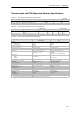
EM 231 Thermocouple Module
The EM 231 Thermocouple module provides a convenient, isolated interface for the S7-200 family
to seven thermocouple types: J, K, E, N, S, T, and R. It allows the S7-200 to connect to low level
analog signals, ±80mV range. All thermocouples attached to the module must be of the same
type.
Thermocouple Basics
Thermocouples are formed whenever two dissimilar metals are electrically bonded to each other.
A voltage is generated that is proportional to the junction temperature. This voltage is small; one
microvolt could represent many degrees. Measuring the voltage from a thermocouple,
compensating for extra junctions, and then linearizing the result forms the basis of temperature
measurement using thermocouples.
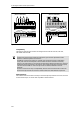
When you connect a thermocouple to the EM 231 Thermocouple Module, the two dissimilar metal
wires are attached to the module at the module signal connector. The place where the two
dissimilar wires are attached to each other forms the sensor thermocouple.
Two more thermocouples are formed where the two dissimilar wires are attached to the signal
connector. The connector temperature causes a voltage that adds to the voltage from the sensor
thermocouple. If this voltage is not corrected, then the temperature reported will deviate from the
sensor temperature.
Cold junction compensation is used to compensate for the connector thermocouple.
Thermocouple tables are based on a reference junction temperature, usually zero degrees
Celsius. The cold junction compensation compensates the connector to zero degrees Celsius.
The cold junction compensation restores the voltage added by the connector thermocouples. The
temperature of the module is measured internally, then converted to a value to be added to the
sensor conversion. The corrected sensor conversion is then linearized using the thermocouple
tables.
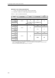
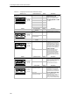
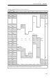
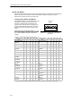
Configuring the EM 231 Thermocouple Module
Configuration DIP switches located on the bottom of the module allow you to select the
thermocouple type, open wire detect, temperature scale, and cold junction compensation. For the
DIP switch settings to take effect, you need to power cycle the PLC and/or the user 24V power
supply.
DIP switch 4 is reserved for future use. Set DIP switch 4 to the 0 (down or off) position. Table A-27
shows other DIP switch settings.