
Specifications

S7-200 Programmable Controller System Manual
424
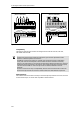
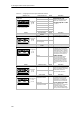
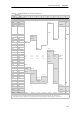
EM 231
AI 2 x RTD
EM 231 Analog Input RTD, 2 Inputs
(6ES7 231--7PB22--0XA0)
A+ A -- B+ B-- C+ C-- D+
24 VDC
power
D--
EM 231
AI 4
EM 231 Analog Input Thermocouple, 4 Inputs
(6ES7 231--7PD22--0XA0)
+--+-- + +-- --
A+ A -- a+ a-- B+ B-- b+ b--
ML+
ML+
+
24 VDC
power
Configuration
Configuration
--
+
--
Figure A-23 Connector Terminal Identification for EM 231 Thermocouple and EM 231 RTD Modules
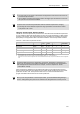
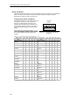
Compatibility
The RTD and Thermocouple modules are designed to work with the CPU 222, CPU 224,
CPU 224XP and CPU 226.
Tip
The RTD and Thermocouple modules are designed to give maximum performance when
installed in a stable temperature environment.
The EM 231 Thermocouple module, for example, has special cold junction compensation
circuitry that measures the temperature at the module connectors and makes necessary
changes to the measurement to compensate for temperature differences between the reference
temperature and the temperature at the module. If the ambient temperature is changing rapidly
in the area where the EM 231 Thermocouple module is installed, additional errors are
introduced.
To achieve maximum accuracy and repeatability, Siemens recommends that the S7-200 RTD
and Thermocouple modules be mounted in locations that have stable ambient temperature.
Noise Immunity
Use shielded wires for best noise immunity. If a thermocouple input channel is not used, short the
unused channel inputs, or connect them in parallel to another channel.