
Specifications

S7-200 Programmable Controller System Manual
420
15
4
MSB LSB
0AQW XX
0
00 0
3
14
Data value 11 Bits
Current output data format
15
3
MSB LSB
AQW XX
0
00 0Data value 12 Bits
Voltage output data format
4
0
0
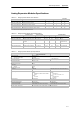
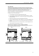
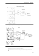
Figure A-20 Output Data Word Format for EM 232 and EM 235
Tip
The 12 bits of the digital-to-analog converter (DAC) readings are left-justified in the output data
word format. The MSB is the sign bit: zero indicates a positive data word value. The four trailing
zeros are truncated before being loaded into the DAC registers. These bits have no effect on the
output signal value.
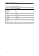
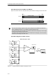
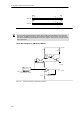
Output Block Diagram for EM 232 and EM 235
DATA
11 0
Vref
D/A converter
Digital-to-analog converter
+
--
R
R
Vout
--10.. +10 Volts
M
Voltage output buffer
+/-- 2V
+
--
+
--
R
Iout
0..20 mA
100
+24 Volt
Voltage-to-current converter
1/4
R
Figure A-21 Output Block Diagram for the EM 232 and EM 235