
Specifications

Technical Specifications Appendix A
419
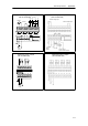
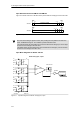
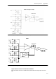
Instrumentation
AMP
GAIN ADJUST
BUFFER
A/D Converter
Input filter
MUX 8 to 1
EM 231 Analog Input, 8 Inputs
Figure A-18 Input Block Diagram for the EM231 Analog Input, 8 Inputs
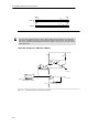
REF_VOLT
C
C
C
A+
RA
A--
Rloop
C
C
C
B+
RB
B--
Rloop
C
C
C
C+
RC
C--
Rloop
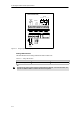
A=1
A=2
A=3
Buffer
+
--
Input filter MUX 4 to 1
BUFFER
DATA
011
A/D Converter
EM 235
A=4
C
C
C
D+
RD
D--
Rloop
GAIN ADJUST
Instrumentation
AMP
+
--
Offset Adjust
R
R
R
R
R
R
R
R
Figure A-19 Input Block Diagram for the EM 235
Output Data Word Format for EM 232 and EM 235
Figure A-20 shows where the 12-bit data value is placed within the analog output word of the
CPU.