
Specifications

S7-200 Programmable Controller System Manual
418
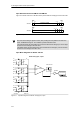
Input Data Word Format for EM 231 and EM 235
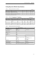
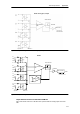
Figure A-16 shows where the 12-bit data value is placed within the analog input word of the CPU.
15 3
MSB LSB
0AIW XX
0
00 0
214
Datavalue12Bits
Unipolar data
15
3
MSB LSB
AIW XX
0
00 0Datavalue12Bits
Bipolar data
4
0
Figure A-16 Input Data W ord Format for EM 231 and EM 235
Tip
The 12 bits of the analog-to-digital converter (ADC) readings are left-justified in the data word
format. The MSB is the sign bit: zero indicates a positive data word value.
In the unipolar format, the three trailing zeros cause the data word to change by a count of eight
for each one-count change in the ADC value.
In the bipolar format, the four trailing zeros cause the data word to change by a count of sixteen
for each one count change in the ADC value.
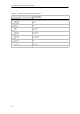
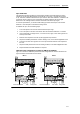
Input Block Diagrams for EM 231 and 235
C
C
A+
RA
A--
Rloop
C
C
C
B+
RB
B--
Rloop
C
C
C
C+
RC
C--
Rloop
A=1
A=2
A=3
Input filter
MUX 4 to 1
BUFFER
011
A/D Converter
A=4
C
C
C
D+
RD
D--
Rloop
GAIN ADJUST
Instrumentation
AMP
+
--
EM 231Analog Input, 4 Inputs
C
R
R
R
R
R
R
R
R
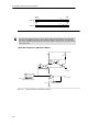
Figure A-17 Input Block Diagram for the EM 231 Analog Input, 4 Inputs