
Specifications

Technical Specifications Appendix A
417
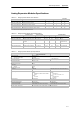
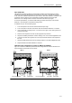
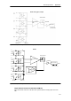
Configuration for EM 235
Table A-22 shows how to configure the EM 235 module using the configuration DIP switches.
Switches 1 through 6 select the analog input range and resolution. All inputs are set to the same
analog input range and format. Table A-22 shows how to select for unipolar/bipolar (switch 6), gain
(switches 4 and 5), and attenuation (switches 1, 2, and 3). In these tables, ON is closed, and OFF
is open. The switch settings are read only when the power is turned on.
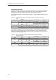
Table A-22 EM 235 Configuration Switch Table to Select Analog Range and Resolution
Unipolar
F
u
l
l
S
c
a
l
e
I
n
p
u
t
R
e
s
o
l
u
t
i
o
n
SW1 SW2 SW3 SW4 SW5 SW6
Full-Scale Input Resolution
ON OFF OFF ON OFF ON 0to50mV 12.5 mV
OFF ON OFF ON OFF ON 0to100mV 25 mV
ON OFF OFF OFF ON ON 0to500mV 125 mV
OFF ON OFF OFF ON ON 0to1V 250 mV
ON OFF OFF OFF OFF ON 0to5V 1.25 mV
ON OFF OFF OFF OFF ON 0to20mA 5 mA
OFF ON OFF OFF OFF ON 0to10V 2.5 mV
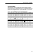
Bipolar
F
u
l
l
S
c
a
l
e
I
n
p
u
t
R
e
s
o
l
u
t
i
o
n
SW1 SW2 SW3 SW4 SW5 SW6
Full-Scale Input Resolution
ON OFF OFF ON OFF OFF +25 mV 12.5 mV
OFF ON OFF ON OFF OFF +50 mV 25 mV
OFF OFF ON ON OFF OFF +100 mV 50 mV
ON OFF OFF OFF ON OFF +250 mV 125 mV
OFF ON OFF OFF ON OFF +500 mV 250 mV
OFF OFF ON OFF ON OFF +1V 500 mV
ON OFF OFF OFF OFF OFF +2.5 V 1.25 mV
OFF ON OFF OFF OFF OFF +5V 2.5 mV
OFF OFF ON OFF OFF OFF +10 V 5mV