
Specifications

S7-200 Programmable Controller System Manual
416
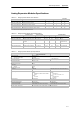
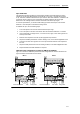
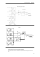
Configuration for EM 231
Table A-20 and Table A-21show how to configure the the EM 231 modules using the configuration
DIP switches. All inputs are set to the same analog input range. In these tables, ON is closed,
and OFF is open. The switch settings are read only when the power is turned on.
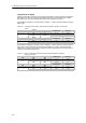
For the EM 231 Analog Input, 4 Inputs module, switches 1, 2, and 3 select the analog input range
(Table A-20).
Table A-20 Configuration Switch Table to Select Analog Input Range for the EM 231 Analog Input,
4 Inputs
Unipolar
F
u
l
l
S
c
a
l
e
I
n
p
u
t
R
e
s
o
l
u
t
i
o
n
SW1 SW2 SW3
Full-Scale Input Resolution
OFF ON 0to10V 2.5 mV
ON
O
N
O
F
F
0to5V 1.25 mV
O
N
ON OFF
0to20mA 5 µA
Bipolar
F
u
l
l
S
c
a
l
e
I
n
p
u
t
R
e
s
o
l
u
t
i
o
n
SW1 SW2 SW3
Full-Scale Input Resolution
O
F
F
OFF ON ±5V 2.5 mV
O
F
F
ON OFF
± 2.5 V 1.25 mV
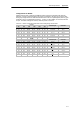
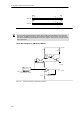
For the EM 231 Analog Input, 8 Inputs module, switches 3, 4, and 5 select the analog input range.
Use Switch 1 and 2 to select the current mode input (Table A-21). Switch 1 ON selects current
mode input for Channel 6; OFF selects voltage mode. Switch 2 ON selects current mode input for
Channel 7; OFF selects voltage mode.
Table A-21 EM 231 Configuration Switch Table to Select Analog Input Range for the EM 231
Analog Input, 8 Inputs
Unipolar
F
u
l
l
S
c
a
l
e
I
n
p
u
t
R
e
s
o
l
u
t
i
o
n
SW3 SW4 SW5
Full-Scale Input Resolution
OFF ON 0to10V 2.5 mV
ON
O
N
O
F
F
0to5V 1.25 mV
O
ON OFF
0to20mA 5 µA
Bipolar
F
u
l
l
S
c
a
l
e
I
n
p
u
t
R
e
s
o
l
u
t
i
o
n
SW3 SW4 SW5
Full-Scale Input Resolution
O
F
F
OFF ON ±5V 2.5 mV
O
F
F
ON OFF
± 2.5 V 1.25 mV