
Specifications

S7-200 Programmable Controller System Manual
414
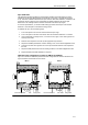
4--20mA
--
0-- 20mA
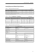
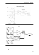
EM 235 Analog Combination 4 Inputs/1 Output
(6ES7 235--0KD22--0XA0)
24
VDC
Power
L+
D--
M
RA A+ A-- RB B+ B-- RC C+ C-- RD D+
+--
Gain
Configuration
M0
Offset
VLOAD
ILOAD
+
V0 I0
250 Ohms (built-in)
PS PS
+--
L+ M
M
Current
Unused
Voltage
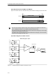
Figure A-14 Wiring Diagrams for Analog Expansion Modules
Analog LED Indicators
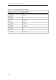
The LED indicators for the analog modules are shown in Table A-19.
Table A-19 Analog LED Indicators
LED Indicator ON OFF
24 VDC Power Supply Good No faults No 24 VDC power
Tip
The state of user power is also reported in Special Memory (SM) bits. For more information, see
Appendix D, SMB8 to SMB21 I/O Module ID and Error Registers.