
Specifications

Technical Specifications Appendix A
411
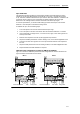
Analog Expansion Modules Specifications
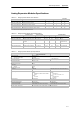
Table A-15 Analog Expansion Modules Order Numbers
Order Number Expansion Model EM Inputs EM Outputs
Removable
Connector
6ES7 231 --0HC22--0XA0 EM 231 Analog Input, 4 Inputs 4 -- No
6ES7 231--0HF22--0XA0 EM 231 Analog Input, 8 Inputs 8 -- No
6ES7 232 --0HB22--0XA0 EM 232 A nalog Output, 2 Outputs -- 2 No
6ES7 232 --0HD22--0XA0 EM 232 Analog Output, 4 Outputs -- 4 No
6ES7 235--0KD22 -- 0XA0 EM 235 Analog Combination 4 Inputs/1 Output 4 1
1
No
1
The CPU reserves 2 analog output points for this module.
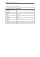
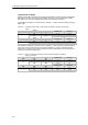
Table A-16 Analog Expansion Modules General Specifications
Order Number
Module Name and
Description
Dimensions (mm)
(W x H x D)
Weight Dissipation
VDC Requirements
+5 VDC +24 VDC
6ES7 231 --0HC22--0XA0 EM 231 A nalog Input, 4 Inputs 71.2 x 80 x 62 183 g 2W 20 mA 60 mA
6ES7 231--0HF22--0XA0 EM 231 Analog Input, 8 Inputs 71.2 x 80 x 62 190 g 2W 20 mA 60 mA
6ES7 232 --0HB22--0XA0 E M 232 Analog Output,
2 Outputs
46 x 80 x 62 148 g 2W 20 mA 70 mA (with both
outputs at 20 mA)
6327 232--0HD22--0X A0 E M 232 Analog Output, 4
Outputs
71.2 x 80 x 62 190 g 2W 20 mA 100 MA (with all
outputs at 20 mA)
6ES7 235--0KD22 -- 0XA0 EM 235 Analog Combination
4 Inputs/1 Output
71.2 x 80 x 62 186 g 2W 30 mA 60 mA (with output
at 20 mA)
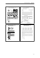
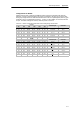
Table A-17 Analog Expansion Modules Input Specifications
General 6ES7 231--0HC22--0XA0
6ES7 235 --0KD22--0XA0
6ES7 231--0HF22--0XA0
Data word format
Bipolar, ful l-scale range
Unipolar, full -scale range
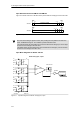
(See Figure A -16)
--32000 to +32000
0 to 32000
DC Input impedance ≥2MΩ voltage i nput
250 Ω current input
>2MΩ voltage input
250 Ω current input
Input filter attenuati on --3dbat3.1Khz
Maximum input vol tage 30 VDC
Maximum input current 32 mA
Resolution
Bipolar
Unipolar
11 bits pl us 1 sign bit
12 bits
Isolation (field to logic) None
Input type Differential Differential v oltage, two channels s electable for
current
Input ranges
Voltage:
Selectable, see Table A-20 for available
ranges
Current:
0to20mA
Voltage:
Channels 0 to 7
0 to +10V, 0 to + 5V and +/--2.5
Current:
Channels 6 and 7
0to20mA
Input resolution See Table A-20 See Table A-22
Analog to digital c onversion ti me < 250 µs < 250 µs
Analog i nput step response 1.5 ms to 95% 1.5 ms to 95%
Common mode rejection 40 dB, DC to 60 Hz 40dB,DCto60Hz
Common mode voltage Signal voltage plus common mode voltage
must be ≤±12 V
Signal voltage plus common mode voltage
must be ≤±12 V
24 VDC suppl y voltage range 20.4 to 28.8 VDC (Clas s 2, Limited Power, or s ensor power from PLC)