
Specifications

S7-200 Programmable Controller System Manual
406
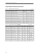
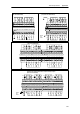
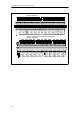
Table A-14 Digital Expansion Modules Output Specifications
G
e
n
e
r
a
l
24 VDC Output Relay Output
1
2
0
/
2
3
0
V
A
C
O
u
t
p
u
t
General
0.75 A 5A 2A 10 A
120/230 VAC Output
Type Solid state-MOSFET (Sourcing) Dry contact Triac, zero-cross turn-on
Rated voltage 24 VDC 24 VDC or 250 VAC 120/230 VAC
Voltage range 20.4 to 28.8 VDC 5to30VDCor
5to250VAC
12 to 30 VDC or
12 to 250 VAC
40 to 264 VAC
(47to63Hz)
24 VDC coi l power v oltage range -- 20.4 to 28.8 V DC --
Surge current (max.) 8 A for 100 ms 30 A 5 A for 4 s @ 10%
duty cycle
15 A for 4 s @
10% duty cycle
5 A rms for 2 AC cycles
Logic 1 (min.) 20 VDC -- L1 (--0.9 V rms)
Logic 0 (max.) 0.1 VDC with
10 K Ω Load
0.2 VDC with 5 K
Ω Load
-- --
Rated current per poi nt (max.) 0.75 A 5A 2.00 A 10 A resistive;
2 A DC inductive;
3 A AC inductiv e
0.5 A AC
1
Rated current per c ommon (max.) 10 A 5A 10 A 10 A 0.5 A AC
Leakage current (max.) 10 µA 30 µA -- 1.1 mA rms at 132 VAC
and 1.8 mA rrms at 264
VAC
Lamp load (max.) 5W 50 W 30 W DC/
200 W AC
4,5
100 W DC/
1000 W AC
60 W
Inductiv e clamp voltage L+ minus 48 V L+ minus 47 V
2
-- --
On state resis tance (contact) 0.3 Ω typical
(0.6 Ω max.)
0.05 Ω max. 0.2 Ω max. when new 0.1 Ω max.
when new
410 Ω max. when load
current is less than
0.05A
Isolation
Optical (galvanic, field to logic)
Coil to logic
Coil to contact
Resis tance (coil to contact)
Isolati on groups
500 VAC for 1 m inute
--
--
--
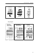
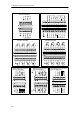
See wiring diagram
--
None
1500 VAC for 1 m inute
100 M Ω min. when new
See wiring diagram
1500 VAC for 1mi nute
--
--
--
1 point
Delay Off to On/On to Off (max.)
Switching (max.)
50 µs / 200 µs
--
500 µs
--
--
10 ms
--
15 ms
0.2 ms + 1/2 AC cycle
--
Switchi ng frequency (max.) -- 1Hz 10 Hz
Lifetime mechanical cycles -- 10,000,000 (no load) 30,000,000
(no load)
--
Lifetime contacts -- 100,000 (rated l oad) 30,000
(rated load)
--
Output on simultaneously All at 55° C (horizontal), All at 45° C(vertical) All at 55 °C
(horizontal) with
20A max. module
current. All at
45°C (vertical) with
20A max. module
current
5.
All at 40
°C (horizontal) with
10A per point
All at 55° C (horizontal),
All at 45° C(vertical)
Connecting two outputs in parallel Yes, only outputs in same group No No
Cable length (max.)
Shielded
Unshielded
500 m
150 m
500 m
150 m
500 m
150 m
1 Load current must be full wave AC and must not be half-wave because of the zero-cross circuitry. Minimum l oad current is 0.05 A AC. With a load current
between 5 mA and 50 mA AC, the current can be controlled, but there is an additional voltage drop due to series resistance of 410 Ohms.
2 If the output overheats due to ex cessive inductive switching or abnormal condi tions, the output point may turn off or be damaged. The output could overheat
or be damaged if the output i s s ubjected to more than 0.7 J of energy switching an inducti ve load off. To eliminate the need for this limitation, a suppression
circui t as described in Chapter 3 can be added in parallel wi th the l oad. These components need to be sized properly for the gi ven application.
3 The EM 222 DO 4 x Relay has a different FM rating than the rest of the S7-200. This module has a T4 rating, instead of T4A for FM Class I, Division Groups
A, B, C, and D Hazardous Locations.
4 Relay lifetime with a lamp load will be reduced by 75% unless steps are taken to reduce the turn-on surge below the surge current rating of the output.
5 Lamp load wattage rating is for rated voltage. Reduce the wattage rating proportionally for voltage being switched (for example 120 VAC -- 100 W).
Warning
When a mechanical contact turns on output power to the S7-200 CPU, or any digital expansion module, it
sends a “1” signal to the digital outputs for approximately 50 microseconds.
This could cause unexpected machine or process operation which could result in death or serious injury to
personnel, and/or damage to equipment.
You must plan for this, especially if you are using devices which respond to short duration pulses.