
Specifications

Technical Specifications Appendix A
405
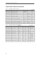
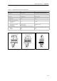
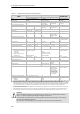
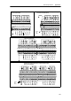
Table A-13 Digital Expansion Modules Input Specifications
General 24 VDC Input 120/230 VAC Input (47 to 63 HZ)
Type Sink/Source (IEC Type 1 sink) IEC Type I
Rated voltage 24 VDC at 4 mA 120 VAC at 6 mA or 230 VAC at 9 mA nominal
Maximum continuous permis sible voltage 30 VDC 264 VAC
Surge voltage (max.) 35 VDC for 0.5 s --
Logic 1 (min.) 15 VDC at 2.5 mA 79 VAC at 2.5 mA
Logic 0 (max.) 5VDCat1mA 20 VAC or 1 mA AC
Input delay (max.) 4.5 ms 15 ms
Connection of 2 wire proxi mity s ensor
(Bero)
Permissible l eakage
current (max .)
1mA 1mAAC
Isolation
Optical (galvanic, field to logic)
Isolati on groups
500 VAC for 1 m inute
See wiring diagram
1500 VAC for 1 minute
1point
Inputs on simultaneously All at 55° C (horizontal), All on at 45° C(vertical)
Cable length (max.)
Shielded
Unshielded
500 m
300 m
500 m
300 m
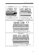
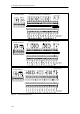
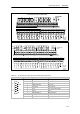
0N .00N
N
L1
120/230 AC Input
24 VDC Input
Used as Sinking Inputs
1M .0 .1 .2 .3
+
1M .0 .1 .2 .3
24 VDC Input
Used as Sourcing Inputs
+
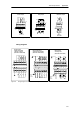
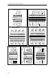
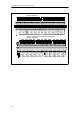
Figure A-7 S7-200 Digital Expansion Modules Inputs