
Specifications

Technical Specifications Appendix A
403
1.1
++
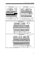
1L 0.0 0.1 0.2 0.3 0.7 1.02L 0.4 0.5 0.6 3L 1.1 1.2 1.3 1.4 1.5 1.6 1.7 N ACL1
0.0 0.1 0.2 0.3 0.4 0.5 0.6 0.71M 1.0 1.1 1.2 1.3 1.4 1.5 1.6 1.7 2.0 2.1 2.2 2.3 2.42M 2.5 2.6 2.7 M L+
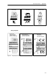
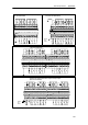
CPU 226 DC/DC/DC (6ES7 216--2AD23--0XB0)
CPU 226 AC/DC/Relay (6ES7 216--2BD23--0XB0)
24 VDC Power
++
++ +
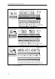
1M 1L+ 0.0 0.1 0.2 0.3 2M 2L+0.4 0.5 0.6 0.7 1.0 1.1 1.2 1.3 1.4 1.5 1.6 1.7 M DCL+
0.0 0.1 0.2 0.3 0.4 0.5 0.6 0.71M 1.0 1.2 1.3 1.4 1.5 1.6 1.7 2.0 2.1 2.2 2.3 2.42M 2.5 2.6 2.7 M L+
N(--)
L(+)
N(--) N(--)
L(+) L(+)
24 VDC Power
24 VDC
Power
Output
24 VDC
Sensor
Power
Output
++
1L+ 0.0 0.1 0.2 0.3 2M 2L+0.4 0.5 0.6 0.7 1.0 1.1 1.2 1.3 1.4 1.5 1.6 1.7 M DCL+
0.0 0.1 0.2 0.3 0.4 0.5 0.6 0.71M 1.0 1.5 1.6 1.7 2.0 2 .1 2.2 2.3 2.42M 2.5 2.6 2.7 M L+
N(--)
L(+)
N(--)
L(+)
120/240 VAC
Power
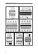
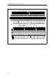
Figure A-6 CPU 226 Wiring Diagrams
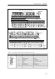
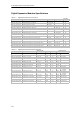
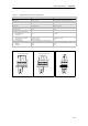
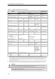
Table A-10 Pin Assignments for the S7-200 Communications Port (Limited Power)
Connector Pin Number PROFIBUS Signal Port 0/Port 1
1 Shield Chassis ground
2 24 V Return Logic common
P
i
n
6
Pin 1
3 RS-485 Signal B RS-485 Signal B
Pin 6
4 Request-to-Send RTS (TTL)
5 5VReturn Logic common
Pin 9
6 +5 V +5 V, 100 Ω series resistor
P
i
n
9
Pin 5
7 +24 V +24 V
8 RS-485 Signal A RS-485 Signal A
9 Not applicable 10-bit protocol select (input)
Connector shell Shield Chassis ground