
Specifications
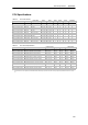
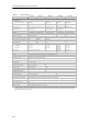
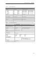
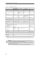

S7-200 Programmable Controller System Manual
400
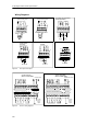
Wiring Diagrams
+
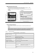
24 VDC Input
Used as Sinking Inputs
1M .0 .1 .2 .3
1M .0 .1 .2 .3
24 VDC Input
Used as Sourcing Inputs
+
Relay Output
1L .0 .1 .2
L(+)
N(--)
24 VDC Output
(Sinking)
1M .0 .1 .2
+
VLOAD
CPU 224 XP and CPU 224XPsi
Analog Input/Output
M I V M A+ B+
ILOAD
--
+
+
--
+
--
InputsOutput
24 VDC Output
(Sourcing)
1M 1L+ .0 .1 .2
+
Figure A-2 CPU Inputs and Outputs
L+
24 VDC
Sensor
Power
Output
24 VDC
Sensor
Power
Output
120/240 VAC Power
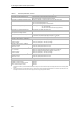
CPU 221 DC/DC/DC
(6ES7 211--0AA23--0XB0)
24 VDC Power
CPU 221 AC/DC/Relay
(6ES7 211--0BA23--0XB0)
ML+
0.0
0.1
0.2 0.3
DC
0.0 0.1 0.2 0.3 2M 0.4 0.5 M L+1M
+
+
+
M
+
1L 0.0 0.1 0.2 2L 0.3 N L1
0.1 0.2 0.3 2M 0.4 0.5 M L+
+
L(+)
N(--)
0.01M
L(+)
N(--)
AC
+
Figure A-3 CPU 221 Wiring Diagrams