Dual-Port Multi-Interface (RS-232/RS-422/RS-485) PCI Bus Serial Card with Send Data Control Model: 3PCI2 Documentation Number 3PCI2-0903 This product designed and manufactured in Ottawa, Illinois USA of domestic and imported parts by International Headquarters B&B Electronics Mfg. Co. Inc. 707 Dayton Road -- P.O. Box 1040 -- Ottawa, IL 61350 USA Phone (815) 433-5100 -- General Fax (815) 433-5105 Home Page: www.bb-elec.com Orders e-mail: orders@bb-elec.
2003 B&B Electronics . No part of this publication may be reproduced or transmitted in any form or by any means, electronic or mechanical, including photography, recording, or any information storage and retrieval system without written consent. Information in this manual is subject to change without notice, and does not represent a commitment on the part of B&B Electronics.
TABLE OF CONTENTS CHAPTER 1: GENERAL INFORMATION...................................... 1 INTRODUCTION ........................................................................................ 1 FEATURES ................................................................................................ 1 QUICK START .......................................................................................... 2 SPECIFICATIONS ......................................................................................
CHAPTER 6: RS-422/RS-485 CONNECTIONS/OPERATION..... 47 RS-422/485 PINOUTS ............................................................................ 47 RS-422 & RS-485 DIFFERENTIAL SIGNALS .......................................... 49 RS-422 OPERATION .............................................................................. 49 RS-485 OPERATION .............................................................................. 50 DTR OPERATION IN RS-485 MODE ................................................
CAUTION: ELECTROSTATIC SENSITIVE DEVICE Use ESD precautions for safe handling. Before removing the card from the anti-static protective packaging: • Discharge any static electricity buildup on your body by touching a large grounded metal surface or the metal chassis on equipment connected to earth ground by a 3-wire power cord. • Avoid touching the gold connectors or other parts on the card except as necessary to set the configuration jumpers.
Chapter 1: General Information Introduction The 3PCI2 Dual Port serial interface card is designed to work with Windows based IBM compatible computers with a PCI bus. The card is Plug and Play compatible which permits the Windows Operating System and driver to set the addresses and IRQ used by the card. If you are developing your own software, make sure that the communications routines support Windows communication drivers and a wide range of COM ports (Com1 to Com16 or higher).
Quick Start CAUTION: ELECTROSTATIC SENSITIVE DEVICE 1. Before removing the card from the anti-static protective packaging, discharge any static electricity on yourself. 2. Set the Operating Mode Jumpers for each port to match the mode desired. Use the Jumper/Mode Table in Chapter 2. 3. Unplug the computer Power Cord to prevent accidentally turning the computer on during installation. 4. Install the Card, replace the cover. 5. Reconnect the Power Cord. 6.
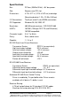
Specifications Bus: PCI bus (33MHz/32-bit) +5V bus power. Slot: Requires one PCI slot Dimensions: 4.79 x 3.77 in (12.16 x 9.57 cm) card edge (Mounting bracket: 1.23 x 12.06 x 0.85 cm) I/O Connections: Two 9-pin male D-sub (DB9M) connectors OS Supported: Windows 95, 98, 2000, XP Baud rates: 460.8K baud maximum - RS-232/422/485 UARTs: 16C950 (128-byte FIFO TX and RX buffers) 16C550 compatible Character length: 5, 6, 7 or 8 bits Parity: Even, odd or none Stop bits: 1, 1.
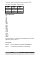
Termination: none. Provision for custom termination (R15/18) Max Power Consumption: All ports loaded Voltage (V) +5 +12 -12 Total Current (mA) 240 <1uA <1 uA 240 Power (W) 1.2 1.2 Typical Baud Rates 75 110 134 150 300 600 1200 1800 2400 4800 7200 9600 14.4K 19.2K 38.4K 57.6K 115.2K 230.4K 460.8K Any baud rate that is a common divisor of 460.8K can be used if the application software supports it.
Chapter 2: Setup Inspection Your 3PCI2 serial card was tested for proper operation before packaging. It should be in perfect mechanical and electrical condition upon receipt. CAUTION: ELECTROSTATIC SENSITIVE DEVICE Use ESD precautions for safe handling. Before removing the card from the anti-static protective packaging: • Discharge any static electricity buildup on your body by touching a large grounded metal surface or the metal chassis on equipment connected to earth ground by a 3-wire power cord.
Selection of Operating Mode The hardware address and IRQ is set by the Windows Operating System using driver information files and the Plug and Play OS. The Operating Mode is set using Jumpers, Device Manager Driver Settings and by your cable connections and software. Set the Jumpers Set JP1 and JP2 Jumpers to match your Operating Mode.
The top jumper sets DB9 connections for either 232 or 422/485. RS-232 operation requires setting only the Top jumper. The middle jumper sets the RS-422/RS-485 transmitter for RS-485 or RS-422 operation. In RS-485 mode, the transmitter is tri-stated when not sending data. In RS-422 mode, the transmitter is always enabled. The bottom jumper sets the RS-422/RS-485 receiver for half-duplex RS-485 operation or full-duplex RS-422/RS-485 operation.
Chapter 3: Software Driver Installation Windows 95 or 98 The 3PCI2 drivers are unique to this series of cards. If at some point in the future, you want to update these drivers, remove these drivers before installing the new version. See Removal at page 17. Windows 98 screens are shown for this section. Windows 95 will have other screen names and text shown. Windows Classic settings used as standard. 1. Configure each port on card and install it – see Chapter 2. 2. Make sure PnP OS is set in the BIOS.
6. Select Search, Click Next. 7. Insert Disc. Select CD-ROM Drive, Click Next. Documentation Number 3PCI2-0903 Manual Chapter 3 9 B&B Electronics Mfg Co – 707 Dayton Rd - PO Box 1040 - Ottawa IL 61350 - Ph 815-433-5100 - Fax 815-433-5104 B&B Electronics Ltd – Westlink Comm. Pk.
Windows will find “B&B 3PCI2 Dual-Port Serial Card” and the driver BBPCI.inf file. 8. Click Next. 9. Click Finish. Installation will complete automatically. 10 Chapter 3 Documentation Number 3PCI2-0903 Manual B&B Electronics Mfg Co – 707 Dayton Rd - PO Box 1040 - Ottawa IL 61350 - Ph 815-433-5100 - Fax 815-433-5104 B&B Electronics Ltd – Westlink Comm. Pk.
Another similar screen will be shown before the above, and after. The second time the above is shown, installation will have completed. Wait for the process to complete. To verify the installation, open Start, Settings, Control Panel, System. Then select the Device Manager Tab. Documentation Number 3PCI2-0903 Manual Chapter 3 11 B&B Electronics Mfg Co – 707 Dayton Rd - PO Box 1040 - Ottawa IL 61350 - Ph 815-433-5100 - Fax 815-433-5104 B&B Electronics Ltd – Westlink Comm. Pk.
Click the Multifunction adapters view the card. If you want other details, Select Properties. Click Ports (COM & LPT) to view the COM numbers assigned by Windows to the card. You will have two new B&B com ports as shown (prior page). Select Properties or double-click on one of the new com ports, to set driver options. Set DTR Operation Set DTR Operation to Normal for RS-232. Set DTR Operation to RS-485 Mode for 2-wire or 4-wire RS-485 operation. Either setting can be used for RS-422.
Changing Com Port Number From the Device Manager, Select Properties, Settings, Advanced. Available names for Com numbers are shown. Select a new number from those not “in use”. Com numbers from Com1 to Com256 may be available. Com numbers “in use” may be used by motherboard ports, modems, virtual com ports for network serial server devices or FAX modem. Formerly installed USB to serial adaptors, PCI cards or other hardware may have reserved a com number.
After selecting a new com number, Click OK, then OK again on the Settings page. After returning to the Device Manager screen, select Refresh. Then double-click Ports again. You should see the two ports renamed as shown below: Example – After renaming B&B Ports from Com5 and Com6 double-click or select each port to finish selecting other properties.
The Default Com parameters are normally overridden by the software application. Continue in Chapter 4, Setting Driver Options, for Data Rate Clock Speed and FIFO settings. Make your connections, RS-232 in Chapter 5, or RS-422/485 in Chapter 6. Documentation Number 3PCI2-0903 Manual Chapter 3 15 B&B Electronics Mfg Co – 707 Dayton Rd - PO Box 1040 - Ottawa IL 61350 - Ph 815-433-5100 - Fax 815-433-5104 B&B Electronics Ltd – Westlink Comm. Pk.
Removal of Drivers/Card If you need to install a possible future driver update or want to remove the card from your system: 1. Open My Computer, Control Panel, System (or Start, Setting, Control Panel, System). 2. Select the Device Manager page. 3. Select the B&B Com port. Click the Remove button. 4. Select the other B&B Com port. Click the Remove button. 5. Click Multifunction Adaptors, then select B&B 3PCI2 DualPort Serial Card which matches the card installed. 6. Click the Remove button.
8. Remove Bbpci.inf in Other subdirectory within INF. If the inf folder can’t be found, select My Computer, View, Folder Options, Files and Folders, select Show all files. Removing the card first in the device manager clears the registry. 8. Shut down the computer. 9. Remove the card. Documentation Number 3PCI2-0903 Manual Chapter 3 17 B&B Electronics Mfg Co – 707 Dayton Rd - PO Box 1040 - Ottawa IL 61350 - Ph 815-433-5100 - Fax 815-433-5104 B&B Electronics Ltd – Westlink Comm. Pk.
Windows 2000 Professional This section covers the first part of device driver installation for Windows 2000 Professional. Windows Classic settings used as standard. The 3PCI2 drivers are unique to this series of cards. If at some point in the future, you want to update these drivers, remove these drivers before installing the new version. See Removal on page 35. 1. Configure each port on the card for the desired RS-232/422/485 mode using the 3 jumpers for each port. See Chapter 2. 2.
6. Select Search and Click Next to continue. 7. Insert the driver disc in the CD-ROM drive. Click Next. Documentation Number 3PCI2-0903 Manual Chapter 3 19 B&B Electronics Mfg Co – 707 Dayton Rd - PO Box 1040 - Ottawa IL 61350 - Ph 815-433-5100 - Fax 815-433-5104 B&B Electronics Ltd – Westlink Comm. Pk.
8. Click Next. 9. Click Finish to complete the first part of installation. 20 Chapter 3 Documentation Number 3PCI2-0903 Manual B&B Electronics Mfg Co – 707 Dayton Rd - PO Box 1040 - Ottawa IL 61350 - Ph 815-433-5100 - Fax 815-433-5104 B&B Electronics Ltd – Westlink Comm. Pk.
10. Next Windows finds a new type of serial port. Click Next. 1 1. Click Next to search a second time. Documentation Number 3PCI2-0903 Manual Chapter 3 21 B&B Electronics Mfg Co – 707 Dayton Rd - PO Box 1040 - Ottawa IL 61350 - Ph 815-433-5100 - Fax 815-433-5104 B&B Electronics Ltd – Westlink Comm. Pk.
12. Select CD-ROM drives. Click Next. 13. Click Next when the bbpci2.inf file is found. 22 Chapter 3 Documentation Number 3PCI2-0903 Manual B&B Electronics Mfg Co – 707 Dayton Rd - PO Box 1040 - Ottawa IL 61350 - Ph 815-433-5100 - Fax 815-433-5104 B&B Electronics Ltd – Westlink Comm. Pk.
14. Click Finish. Wait for the process to complete. Check and verify that a new B&B Com port is now available. 13. Open Start, Settings, Control Panel, System. Then select the Hardware tab on System Properties. 14. Skip over the first part of software driver installation for XP which follows. The second part applies to both 2000 and XP.
Windows XP Professional This section covers the first part of device driver installation for Windows XP Professional. Windows Classic settings used as standard. The 3PCI2 drivers are unique to this series of cards. If at some point in the future, you want to update these drivers, remove these drivers before installing the new version. See Removal on page 35. 1. Configure each port on the card for the desired RS-232/422/485 mode using the 3 jumpers for each port. See Chapter 2. 2.
6. Windows will find the drivers on the CD, then provide a notice concerning Windows Logo testing for XP. This new feature of XP simply indicates that these drivers have not yet undergone the Microsoft testing procedures required to use the Windows XP Logo on the packaging. Driver compatibility is not affected. 7. Click Continue Anyway.
8. Click Finish to continue installation. 9. Select Next. 26 Chapter 3 Documentation Number 3PCI2-0903 Manual B&B Electronics Mfg Co – 707 Dayton Rd - PO Box 1040 - Ottawa IL 61350 - Ph 815-433-5100 - Fax 815-433-5104 B&B Electronics Ltd – Westlink Comm. Pk.
10. Windows provides the Logo notice for Com Port Driver. 11. Click Continue Anyway. Documentation Number 3PCI2-0903 Manual Chapter 3 27 B&B Electronics Mfg Co – 707 Dayton Rd - PO Box 1040 - Ottawa IL 61350 - Ph 815-433-5100 - Fax 815-433-5104 B&B Electronics Ltd – Westlink Comm. Pk.
12. Click Finish. Repeat Step 9, 10, 12 for second Com Port. 13. After Finish for the second Com port on the card, this part of software driver installation is complete. Check and verify that a new B&B Com port is now available within the Control Panel, System, Device Manager. If you are more familiar with Windows 95/98/2000, you may want to select the Windows Classic look for the Start Menu. Position the mouse pointer over the Taskbar, then Right Click, Select Properties.
System Properties/Hardware/Device Manager Select Device Manager, then view the hardware list. Documentation Number 3PCI2-0903 Manual Chapter 3 29 B&B Electronics Mfg Co – 707 Dayton Rd - PO Box 1040 - Ottawa IL 61350 - Ph 815-433-5100 - Fax 815-433-5104 B&B Electronics Ltd – Westlink Comm. Pk.
Under Multifunction Adapters, the B&B 3PCI2 Dual-Port Serial Card is installed. Under Ports, B&B Com Port (COM6) and (COM7) was assigned. If Com ports between COM1 and COM6 are not “in use” by other hardware or software, we can change the B&B Com port to another available Com number using Properties, Settings, Advanced. Double-click on COM6 to access the Properties. Next select Settings.
Set DTR Operation Set DTR Operation to Normal for RS-232. Set DTR Operation to RS-485 Mode for 2-wire or 4-wire RS-485 operation. Either setting can be used for RS-422. The card jumpers must be set for the same mode. See Chapter 2. The Default Com parameters are normally overridden by the software application. You can now remove the driver disc, close the Windows, and check the new ports with your software.
Changing Com Port Number From the Device Manager, Select Properties, Settings, Advanced. Available names for Com numbers are shown. Select a new number from those not “in use”. Com numbers from Com1 to Com256 may be available. Com numbers “in use” may be used by motherboard ports, Modems, virtual com ports for network serial server devices or FAX modem. Formerly installed USB to serial adaptors, PCI cards or other hardware may have reserved a com number.
Advanced editing of the registry may needed to clean up the problem. Special permissions are required with 2000 or XP. After selecting a new com number, Click OK, then OK again on the Settings page. After returning to the Device Manager screen, it should refresh automatically. Then double-click Ports again. You should see a B&B port renamed as shown below: Example – After renaming B&B Port to Com2 & Com4 Double-click or select the port to finish selecting other properties.
Make your connections, RS-232 in Chapter 5 or RS-422/485 in Chapter 6. Removal of Drivers/Card If you need to install a possible future driver update or want to remove the card from your system: 1. Click on the B&B Com Port under Ports (COM & LPT) and select Uninstall (right click). 2. Click on Multifunction Adapters, select the B&B 3PCI2 Dual-Port Serial Card. Select Uninstall. This step cleans the entries in the Registry which cannot be easily edited under 2000 or XP. 3.
Windows Explorer, WINNT, INF, Oem2 and Oem3 files. Finding the OEMx.inf and OEMx.PNF files for removal. Continued next page Documentation Number 3PCI2-0903 Manual Chapter 3 35 B&B Electronics Mfg Co – 707 Dayton Rd - PO Box 1040 - Ottawa IL 61350 - Ph 815-433-5100 - Fax 815-433-5104 B&B Electronics Ltd – Westlink Comm. Pk.
Show Hidden Files and Folders End of Removal section. 36 Chapter 3 Documentation Number 3PCI2-0903 Manual B&B Electronics Mfg Co – 707 Dayton Rd - PO Box 1040 - Ottawa IL 61350 - Ph 815-433-5100 - Fax 815-433-5104 B&B Electronics Ltd – Westlink Comm. Pk.
Chapter 4: Setting Driver Options DTR Operation Example - DTR Operation Screen (Windows 98) Select Normal for RS-232 operation. Select RS-485 Mode for Automatic RS-485 Driver Control. Use either setting for RS-422 operation. Continued next page Documentation Number 3PCI2-0903 Manual Chapter 4 37 B&B Electronics Mfg Co – 707 Dayton Rd - PO Box 1040 - Ottawa IL 61350 - Ph 815-433-5100 - Fax 815-433-5104 B&B Electronics Ltd – Westlink Comm. Pk.
Advanced – Com Port Renaming Select to change port name to another Com number. From the Device Manager, Select Properties, Settings, Advanced. Example - Advanced Settings (Windows 98) Available names for Com numbers are shown. Select a new number from those not “in use”. Com numbers from Com1 to Com256 may be available. Com numbers “in use” may be used by motherboard ports, Modems, virtual com ports for network serial server devices or FAX modem.
Data Rate - 1X or 4X Clock Speed Each 3PCI2 port in the Device Manager has Data Rate, Clock Speed settings for normal 1X or 4X. The 4X position provides a compatibility mode for software which requires it. In the 4X position, all specified baud rate settings are multiplied 4 times. For example, if the software specifies 57.6K baud, the actual baud rate will be 230.4K baud, 115.2K becomes 460.8K baud. Each port can be set separately.
FIFO Settings The default FIFO settings should minimize overhead and work well for most users. The FIFO Interrupt Trigger levels setting determines how often the host processor services the serial port to send or receive data. The Transmitter Trigger level sets how low the output buffer gets before it triggers a request for more data from program memory. The Receiver Trigger level sets how much data is in the input buffer before it triggers a request to read the data from the buffer to program memory.
The optimum setting for each depends on the nature of your data, how it fits within the buffer, how fast your computer operates, etc. Receiver FIFO applies when Handshaking is used for Hardware or Software control. For Connections, refer to Chapter 5, RS-232 or Chapter 6, RS-422 or RS-485. Documentation Number 3PCI2-0903 Manual Chapter 4 41 B&B Electronics Mfg Co – 707 Dayton Rd - PO Box 1040 - Ottawa IL 61350 - Ph 815-433-5100 - Fax 815-433-5104 B&B Electronics Ltd – Westlink Comm. Pk.
Chapter 5: RS-232 Connections/Operation The DB-9 male connectors on the card are configured as standard RS-232 (DTE) serial ports. Table 3 shows the signal names and pin numbers.
There are two types of RS-232 ports, DTE (Computer) and DCE (Modem). Connected directly together using a modem cable wired pin to pin, the inputs match the outputs of the other. When two of the same type (DTE to DTE or DCE to DCE) are interconnected, a crossover (null modem) cable is needed to route the outputs of one to the inputs of the other. This type of cable is needed to interconnect two computers with RS-232.
Chapter 6: RS-422/RS-485 Connections/Operation These modes support 2 channels - transmit and receive. The pinouts of the DB-9 male connector are given in Table 4. Table 4: RS-422/485 Pinouts Name Description Direction DB9M Pin Receive Data A Input RD(A) − TD(B) + Transmit Data B Output Transmit Data A Output TD(A) − GND Signal Ground -----RD(B) + Receive Data B Input Connect only to specified pins for proper operation. 1 2 3 5 9 2-Wire RS-485 Connections Fig. 6.
4-Wire RS-422 or RS-485 Connections Figure 6.2 Note: With RS-422 Devices, connect only one device to computer. Connect the TD(B) pin #2 on the computer to RD(B) on the device. Connect the TD(A) pin #3 on the computer to RD(A) on the device. Connect the RD(B) pin #9 on the computer to TD(B) on the device. Connect the RD(A) pin #1 on the computer to TD(A) on the device. Connect the Signal Ground pin #5 to Signal Ground on the device.
Figure 6.3 RS-422 & RS-485 Differential Signals In RS-422 and RS-485 modes each signal is differential. When one line is high (4.4V) the other is low (0V), they alternate voltage with data. The receiver is differential so that common mode noise picked up on the twisted pair of wires is cancelled. Receiver sensitivity is rated at 200mV. A separate signal ground/common connection provides a common mode reference for the transmitter and receiver.
This limitation is due to the fact that the transmitter is active all the time, and the line pair is set so that the TD(B) line is high during Mark state, and the TD(A) line is set low. If another transmitter output is connected to the same wire pair, and attempts to send data by setting the line pair to Space state, the first transmitter is still trying to hold the opposite state and neither can communicate.
The RS-485 mode is set using 3 jumpers per port, and by selecting the RS-485 Mode for DTR Operation on that com port. RS-485 Network Biasing In an RS-485 network, the transmitter tri-states to a high impedance state. Unlike RS-422 where the transmitter holds the TD(B) line high and the TD(A) line low (Mark state) when not transmitting data. To establish and maintain the Mark state for all RS-485 receivers, Biasing is required.
Chapter 7: Troubleshooting If you have any trouble starting your system after installing the card, the card may not be properly seated in the slot. Remove and reinsert it or try a different slot. Check that BIOS is set for PnP OS. If you are unable to communicate with the card using your software and hardware devices: 1. Check your pinouts In RS-422 or RS-485 mode the "A" lines should match your "A" or "−" lines. "B" lines should match your "B" or "+" lines. Note: RS-422/485 pinouts are non-standard. 2.
3. Run Setup.exe to install COMTest on your program menu under B&B Electronics. 4. Check your Card Jumpers, and Driver Settings. See Chapter 2. 5. Make sure you have DTR Operation set to the correct mode. Normal for RS-232, RS-485 Mode for RS-485. RS-422 mode works in either setting provided that the mode jumpers are set correctly. 6. A loopback connection for RS-232 connects the Transmit output to the Receive input (pins #2 & #3 on the DB9 connector). Use connections below to check all. Fig. 7.
Fig. 7.3 RS-485 Connections for 2-Wire Mode 8. To check 2-wire RS-485, you must either enable the receiver by moving the receive jumper to RX ENABLE mode (Table 1), or use one port to transmit to another by cross connecting (Fig. 7.3) and loading COMTest twice, one copy for each port. Characters typed in one copy of COMTest will appear in the receive window of the other.
Appendix A: Jumper/Mode Settings Set JP1 and JP2 Jumpers to match your Operating Mode. Port 1 (bottom connector) Port 1 Jumpers JP1 Top JP1 Middle JP1 Bottom RS-232 RS-422 4-Wire RS-485 4-Wire RS-485 2-Wire 232 422/485 422/485 422/485 (Right) ----No effect ----No effect (left) TX ENABLE (right) RX ENABLE (right) (left) TX SD (left) RX ENABLE (right) (left) TX SD (left) RX SD (left) Table A.
Appendix B: Connector Pinouts Table B.1: RS-232 Pinouts Name Description Direction (DTE) DCD RD TD DTR GND DSR RTS CTS RI Data Carrier Detect Receive Data Transmit Data Data Terminal Ready Signal Ground Data Set Ready Request to Send Clear to Send Ring Indicator Input Input Output Output -----Input Output Input Input DB9M Pin 1 2 3 4 5 6 7 8 9 Table B.
Table B.3: RS-422/485 Pinouts Name Description Direction DB9M Pin Receive Data A Input 1 RD(A) − TD(B) + Transmit Data B Output 2 Transmit Data A Output 3 TD(A) − GND Signal Ground -----5 RD(B) + Receive Data B Input 9 With 2-wire RS-485 mode operation, your connection cable must jumper TD(A) to RD(A) and TD(B) to RD(B). Connect from TD(A) and TD(B) to the Data A(− −) and Data B(+) wires of your RS-485 network. See Chapter 6 for example connections.
Appendix C: Troubleshooting With ComTest Included on the CD-ROM disc is a test program called ComTest. See Chapter 7. ComTest is a simple 32-bit Windows (Windows 95, 98, 2000, XP or NT 4.0) COM port test program. It allows multiple ports at any address and IRQ, to be opened at any given time. ComTest can also be found on our Support webpage at: www.bb-elec.com. B&B Com Test • A Windows Terminal Program for Simple Checks of Serial Ports. Works with USB Serial Converters & ISA or PCI Serial Cards.
Start ComTest 1. Make loopback connections. 2. Select Start, Programs, B&B Electronics, ComTest, ComTest. 3. ComTest Starts with a Select Port Window. 4. Select the Com port to access or test. (The drop down box shows available ports not in use). 5. Click Ok. Configure Port is shown. 6. Select the needed baud rate, parity, data bits, stop bits. (Defaults are common settings). 7. Type characters – they will appear in the upper window. 8.
Appendix D: Declaration of Conformity Statement DECLARATION OF CONFORMITY Manufacturer’s Name: Manufacturer’s Address: B&B Electronics Manufacturing Company P.O. Box 1040 707 Dayton Road Ottawa, IL 61350 USA Model Numbers: 3PCI2 Description: 2-port RS232/422/485 PCI Serial Card Type: Light industrial ITE equipment Application of Council Directive: 89/336/EEC Standards: EN 55022 EN 50082-1 EN 61000 (-4-2, -4-3, -4-4, -4-6) William H.