
I/O Module User's Manual


Analog Input module
4-
30
ADAM 5000 IO modules User’s Manual
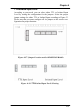
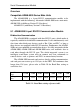
Features--Digital Output Mapping
If users want to use Digital Output function, ADAM utility is
available for setting specifically which module, channel or slot to
receive the alarm signals.
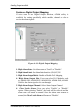
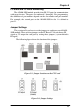
Figure 4-36: Digital Output Mapping
1: High Alarm State--Set Alarm state to "Latch" or "Disable".
2: High Alarm Limit--Set Alarm limit from 0 to 4,294,967,295.
3: High Alarm Output Mode--Enable or Disable D.O. Mapping.
4: High Alarm Output Slot--Users can select D.O Modules such
as ADAM-5050, ADAM-5055, ADAM-5056, ADAM-5060, ADAM-
5068 for the alarm signal to be sent through.
5: High Alarm Output Channel--Select Alarm Output Channel
6: Clear Latch Alarm--Users can select "Enable" or "Disable"
option. When selecting "Enable", the latch will be relieved and the
alarm state will return to normal. Once the alarm state returns to
normal, the Clear Latch Alarm will return to "Disable".