Distributed Smart Switch Model 485DSS Document No. 485DSS3298 This product Designed and Manufactured In Ottawa, Illinois USA of domestic and imported parts by B&B Electronics Mfg. Co. Inc. 707 Dayton Road -- P.O. Box 1040 -- Ottawa, IL 61350 PH (815) 433-5100 -- FAX (815) 434-7094 Internet: http://www.bb-elec.com sales@bb-elec.com support@bb.elec.
TABLE OF CONTENTS CHAPTER 1: HARDWARE ...................................................................1 INTRODUCTION .........................................................................................1 Figure 1. Example of an RS-485/422 Multi-Node Network.......................1 CHECKLIST ...............................................................................................1 SPECIFICATIONS ........................................................................................2 Figure 2.
APPENDIX C: CABLE CHARTS ......................................................C-1 CHART 1. IBM PC DB25 CONNECTOR TO ..........................................C-1 485DSS RS-232 (DTE) PORT ...........................................................C-1 CHART 3. RS-232 DCE DEVICE W/DB25 CONNECTOR TO ..................C-1 485DSS RS-232 (DTE) PORT ...........................................................C-1 CHART 2. IBM PC DB9 CONNECTOR TO ............................................
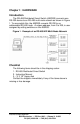
Chapter 1: HARDWARE Introduction The RS-485 Distributed Smart Switch (485DSS) connects one RS-232 device to an RS-485 multi-node network as shown in Figure 1. To accomplish this, the 485DSS converts RS-232 to an addressable RS-485 node. A unique address, from 0 to 255, is user assigned by setting switches on the 485DSS. Figure 1. Example of an RS-485/422 Multi-Node Network Checklist The following items should be in the shipping carton: 1. RS-485 Distributed Smart Switch 2. Instruction Manual 3.
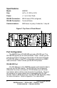
Specifications Model: 485DSS Size: 4.8"L x 2.15"W x 0.9"H Power: +11 to 16 Vdc 75mA RS-232 Connection: DB-25 male (DTE configured) RS-485 Connection: Terminal Blocks Communications: 9600 baud, no parity, 8 data bits, 1 stop bit Figure 2. Top View of Circuit Board Port Configuration The 485DSS has a RS-485/422 port and a RS-232 port. The RS-485/422 signals are on terminal blocks. Table 1 shows you the pinouts and Figure 2 shows you the location of the terminal blocks.
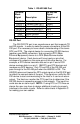
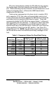
Table 1. RS-422/485 Port Terminal Block Signal FR GND TD(A)(-) TD(B)(+) RD(A)(-) RD(B)(+) GND +12VDC Description Frame Ground Transmit Data (A)(-) Transmit Data (B)(+) Receive Data (A)(-) Receive Data (B)(+) Signal Ground Power Supply RS-422/485 Signal Direction of Port <------> Output Output Input Input <------> Input RS-232 Port The RS-232 DTE port is an asynchronous port that supports TD and RD signals. In order to make the proper connections to the RS232 port.
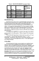
Table 2. RS-232 DTE DB25P Connector Chart Pin # 1 2 3 4 5 7 Signal FR GND TD RD RTS CTS SG Description Frame Ground Transmit Data Receive Data Request to Send Clear to Send Signal Ground Signal Direction of RS-232 DTE Port <------> Output Input Output Input <------> RS-422/485 Wiring RS-485 receivers also have an enable/disable control line. The 2W/4W jumper selects when to enable and disable RS-485 receiver.
SD control automatically enables the RS-485 driver by sensing the leading edge of the first character transmitted to the RS-232 port. After transmitting the last character, the send data timer circuit waits one character time (1 millisecond at 9600 baud) before disabling the RS-485 driver. There are two components in the timer circuit, a resistor (R15) and a capacitor (C10), that make up the send data control circuit.
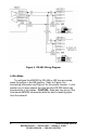
Figure 3. RS-485 Wiring Diagram 4-Wire Mode To configure the 485DSS for RS-485 or 422 four-wire mode, place the jumper in the 4W position. Refer to Figure 4 for connecting information and Figure 2 for the jumper location. In this position on a 4-wire network the Host and the RS-232 device can communicate in full duplex.
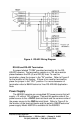
Figure 4. RS-422 Wiring Diagram RS-485 and RS-422 Termination A jumper labeled “TERM” provides termination for the RS485/422 receiver. The termination resistor is a 120-ohm resistor placed between the RD (A) and RD (B) lines. To use this termination, place the jumper in the "IN" position. Refer to Figure 2 for the location of this jumper. If there is no need for termination, place the jumper in the "OUT" position.
Operation The host computer of the RS-485 network controls each 485DSS on the network by sending them command messages. These commands can turn a 485DSS on or off, and can also request status from an individual or from all of the 485DSS's on the network. The communication setup used to send and receive these commands are: 9600 baud, 8 data bits, no parity, and 1 stop bit. Each command consists of four characters: a start of message character, two address characters, and the command character.
Figure 5. Simplified Functional Diagram Three red LED indicators are located on top of the 485DSS. The LED labeled TD flashes when the RS-232 device is transmitting data. The LED labeled RD flashes when data is being received by the 485DSS from the RS-485 network. The LED labeled SEL turns on indicating that the RS-232 device has access to the RS-485 network. Refer to Figure 2. Terminal blocks on the 485DSS connect the RS-485 signals, and input power to the unit.
The Command String All Command Strings consist of four ASCII characters. The first character is the start of message character, "X-off" (decimal 19). The second and third characters represent the hexadecimal address of an individual 485DSS. The address range is from 0 to 255 (HEX "00" to "FF"). Some commands require the use of the broadcast character "DC2" (decimal 18) as the second and third characters in the command. The fourth character is the command character.
If you were writing a program in BASIC to turn on address 10 decimal (0A hexadecimal) you might form a string like this: DSS0AON$ = CHR$(19) + "0" + "A" + CHR$(1) You could then send DSS0AON$ to select 485DSS address 10 (0A hex). Use similar strings for turning on the other 485DSS's. OFF Command This command turns off all 485DSS's on the network and lowers the RTS output handshake line on pin 4 of the DB25 connector. The command string consists of all non-printable ASCII characters.
in the address field specifies all 485DSS's on the network. This command temporarily turns off (disconnect) the RS-232 port from the network while transmitting the reply message. The reply message transmitted by the 485DSS consists of six ASCII characters. The first character is the acknowledge character, an upper case "A" (decimal 65). The second and third characters represent the hexadecimal address of the 485DSS that sent the message. The address range is from 0 to 255 (HEX "00" to "FF").
Example: A unit with a decimal address of ten will have a delay of 220 milliseconds [(10 x 0.02) + 0.02 = 0.22 seconds]. Command character: ACK (decimal 6) Example 1: To request status from the 485DSS set to address 11 ( 0B hex) decimal. HOST transmits: Xoff “0” “B” ACK ( 19 48 66 6 decimal) ( 13 30 42 6 hex) Reply: “A” “0” “B” “0” “1” cr The reply indicates that the RS-232 port has no connection to the network on unit 11 and the CTS handshake line is in the high state.
If you were writing a program in BASIC to request status from address 5 decimal, you might form a string like this: DSS05RS$ = CHR$(19) + "0" + "5" + CHR$(6) You could then send DSS05RS$ to request status from 485DSS address 5. Use similar strings for requesting status from other individual 485DSS's.
Example 1: To set the address to decimal 21 (15 hex), you would turn on switches 1, 3, and 5 (1 + 4 + 16 = 21). Example 2: To set the address to 123 decimal (7B hex), turn on switches 1, 2, 4, 5, 6, and 7 (1 + 2 + 8 + 16 + 32 + 64 = 123). NOTE: It is important that the address you select is not already being used on the network! Binary File Transfer When transmitting binary files through the Distributed Smart Switch, it is possible that a string of characters could resemble a 485DSS command message.
Chapter 2: SOFTWARE Description The Distributed Smart Switch Demonstration (DSS_DEMO) Program (IBM PC or Compatible) provides the user with examples of how to receive and transmit commands to the 485DSS. The DSS_DEMO.EXE is a DOS executable program written in QuickBasic that will send turn on, turn off, and status request commands to the 485DSS. The program also monitors reply messages from any or all 256 addresses. The source code is written in QuickBasic (DSS_DEMO.BAS), Borland Pascal (DSS_DEMO.
Running Demonstration Program Before you can run the demonstration program, you must run the install program described in the “Hard Drive Installation” section above. Make sure you have made the proper connections from the 485DSS to the RS-485 communication lines. If you are running Windows, exit Windows to DOS. To run the program follow these steps from the DOS prompt: QuickBasic Program 1. Type CD \485DSS and press the key. 2. Type DSS_DEMO and press the key. C Demo Program 1.
Appendix A: ASCII Character Codes DECIMAL to HEX to ASCII CONVERSION TABLE DEC HEX ASCII KEY DEC HEX ASCII DEC HEX ASCII DEC HEX ASCII 0 0 NUL ctrl @ 32 20 SP 64 40 @ 96 60 ` 1 1 SOH ctrl A 33 21 ! 65 41 A 97 61 a 2 2 STX ctrl B 34 22 “ 66 42 B 98 62 b 3 3 ETX ctrl C 35 23 # 67 43 C 99 63 c 4 4 EOT ctrl D 36 24 $ 68 44 D 100 64 d 5 5 ENQ ctrl E 37 25 % 69 45 E 101 65 e 6 6 ACK ctrl F 38 26 & 70 46 F 102 66 f 7 7 BEL
Appendix B: Decimal/Hexadecimal/Conversions The decimal (base 10) numbering system represents each position in successive powers of 10, with each decimal symbol having a value from 0 to 9. The hexadecimal (base 16) numbering system represents each position in successive powers of 16 with each hex symbol having a value of 0 to 15. Since each hex position must have a single symbol, the symbols "A" through "F" are assigned to values 10 through 15 respectively. Refer to Table 1.
Hexadecimal to Decimal Conversion: Each “Hex digit” is the decimal equivalent value of the hexadecimal symbol. Example: Convert 10FC hexadecimal to decimal. Decimal = (1st Hex digit x 4096) + (2nd Hex digit x 256) + (3rd Hex digit x 16) + (4th Hex digit) 1 0 15 12 x x x x 4096 256 16 1 = = = = 4096 0 240 12 4348 10FC hex equals 4348 decimal. 4348 decimal equals 10FC hexadecimal. Decimal to Hexadecimal Conversion: Example: Convert 4348 decimal to hexadecimal. 4348 decimal equals 10FC hexadecimal.
Appendix C: Cable Charts These charts indicate some common cable wiring based on the 485DSS RS-232 and RS-485/422 ports. Refer to the Port Configuration section of this manual for more information. Chart 1. IBM PC DB25 Connector to 485DSS RS-232 (DTE) Port IBM PC 485DSS Serial Port Signal RS-232 (DTE) Port DB25 Connector Direction DB25 Connector 2 -----------> 3 3 <----------2 4 -----------> 5 5 <----------4 7 <---------> 7 Chart 2.
Chart 4. RS-232 DCE Device w/DB9 Connector to 485DSS RS-232 (DTE) Port RS-232 DCE 485DSS Serial Port Signal RS-232 (DTE) Port DB9 Connector Direction DB25 Connector 2 -----------> 3 3 <----------2 5 <---------> 7 7 <----------4 8 -----------> 5 Chart 5. RS-422/485 4-Wire Device to 485DSS RS-422/485 Port.
FEDERAL COMMUNICATIONS COMMISSION RADIO FREQUENCY INTERFACE STATEMENT Class A Equipment This equipment has been tested and found to comply with the limits for Class A digital device, pursuant to Part 15 of the FCC Rules. These limits are designed to provide reasonable protection against harmful interference when the equipment is operated in a commercial environment.