
User's Manual


Documentation Number 232OPSDA1397 Manual 5
B&B Electronics -- PO Box 1040 -- Ottawa, IL 61350
PH (815) 433-5100 -- FAX (815) 433-5105
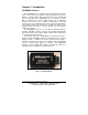
Chapter 2: Connections
This chapter will cover the connections required for the
232OPSDA. Four sets of connections are required: A/D converter,
digital I/O, serial port, and power supply connections. Do not make
any connections until you have read this chapter. If you do not use a
particular type of connection, it is still important to read each section.
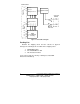
Table 2.1 shows the terminal block assignments.
Table 2.1: Terminal Block Assignments
* The current loop input uses a non-inverting amplifier that has a
gain of 23.064. Space for through-hole resistors is provided to
change the gain. By decreasing the gain, currents up to 100mA can
be read with A/D 0.
** This A/D input uses a voltage follower circuit. Spaces for through-
hole resistors are provided to convert the voltage follower into a non-
inverting amplifier with gain > 1.
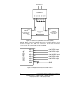
A/D Connections
The A/D connections are made on the I/O port which consists of
ten terminal blocks. Terminal Blocks 0-5 are A/D channels 0-5.
These six A/D channels are referenced to GND (terminal block 8).
The 4-20mA Current Loop A/D channel requires connections
different from the other five channels, so two different diagrams are
shown for required A/D connections. Figure 2.1 shows the
connections required for the 4-20mA Current Loop channel (A/D 0),
and Figure 2.2 shows the connections required for A/D channels 1-
5.
Terminal
Block
Function Description
TB 0 A/D 0
4-20mA Current Loop Input Channel*
TB 1 A/D 1
Buffered 0 to 5V A/D Channel**
TB 2 A/D 2 Buffered 0 to 5V A/D Channel
TB 3 A/D 3 0 to 10V A/D Channel
TB 4 A/D 4 Non-buffered 0 to 5V A/D Channel
TB 5 A/D 5 Non-buffered 0 to 5V A/D Channel
TB 6 Digital out Digital Output
TB 7 Digital in Digital Input
GND GND Ground
+12VDC +12VDC Power Supply Connection