Not Recommended for New Installations. Please contact Technical Support for more information. Asynchronous to Synchronous Converter Model 2010 Documentation Number 2010AS3297 B&B Electronics Mfg. Co. Inc. 707 Dayton Road -- P.O. Box 1040 -- Ottawa, IL 61350 PH (815) 433-5100 -- FAX (815) 433-5105 Internet: http://www.bb-elec.com orders@bb-elec.com support@bb.elec.
Table of Contents 1.0 WARRANTY INFORMATION................................................... 1 1.1 RADIO AND TV INTERFERENCE ....................................... 1 1.2 SERVICE .............................................................................. 1 2.0 GENERAL INFORMATION ...................................................... 2 2.1 FEATURES........................................................................... 2 2.2 DESCRIPTION ................................................................
1.0 WARRANTY INFORMATION B&B Electronics warrants all Model 2010 components to be free from defects, and will—at our option—repair or replace the product should it fail within one year from the first date of shipment. This warranty is limited to defects in workmanship or materials, and does not cover customer damage, abuse or unauthorized modification. If this product fails or does not perform as warranted, your sole recourse shall be repair or replacement as described above.
2.0 GENERAL INFORMATION Thank you for your purchase of this B&B Electronics product. This product has been thoroughly inspected and tested and is warranted for one year parts and labor. If any questions or problems arise during installation or use of this product, please do not hesitate to contact B&B Electronics Technical Support at (815) 433-5100. 2.1 FEATURES • • • • • • • • • Conforms to CCITT V.14 and V.
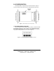
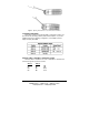
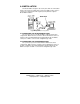
3.0 CONFIGURATION The Model 2010 is configured using four internal switches. Figure 1 shows the switch locations with respect to other PC board components. Figure 1. Switch locations on the 2010 PC board 3.1 SETTING INTERNAL SWITCHES The four switches shown in Figure 2 allow selection of character length and extended signaling rate. These switches are located internally on the Model 2010's PC board. To access them use a small flathead screwdriver to pop open the Model 2010's case as shown in Figure 3.
Figure 3. Opening the Model 2010’s case with a small screwdriver 3.2 SWITCH SETTINGS All possible settings for the Model 2010's configuration switches are presented in the following summary table and descriptions. If you have additional questions regarding configuration, contact B&B Technical Support at (815) 433-5100. Switches SW1-1 and SW1-2: Character Length Switches SW1-1 and SW1-2 are set in combination to determine the character length for asynchronous data.
Switch SW1-3: Extended Signaling Rate (ESR) The setting for switch 1-3 determines the range of variability the Model 2010 looks for in asynchronous data rates (i.e., the actual variance from a given frequency level the Model 2010 will tolerate). SW 1-3 Off -2.5% to +1% On -2.5% to +2.
4.0 INSTALLATION The Model 2010 is designed to be used in pairs, with one unit installed between an asynchronous DTE and a synchronous DCE on either end of a synchronous communication link. Figure 4 (below) illustrates a typical Model 2010 installation. Figure 4. Typical Model 2010 application 4.1 CONNECTING THE ASYNCHRONOUS PORT The asynchronous port of the Model 2010 is a DB-25 female and is configured as "DCE". Therefore, it wants to talk to a DTE device such as a terminal or PC.
APPENDIX A: SPECIFICATIONS Data Rates: Up to 19.2 Kbps Clocking: Provided by modem or multiplexer Buffer: 4 bit RTS override feature empties buffers before dropping RTS, making the Model 2010 usable in a polling environment Data Transmission: Full or half duplex Connectors: Async.: DB-25 female Sync.: DB-25 male Power: No external power required; uses power from data and control signals Temperature Range: 0-60°C (32-140°F) Altitude: 0-15,000 feet Humidity: Up to 95% non-condensing Dimensions: 3.2" x 2.
APPENDIX B: ASYNCHRONOUS PORT CONNECTIONS (CONFIGURED AS “DCE”) Pin Name Description 1 FG Frame Ground; connected straight to synchronous port 2 TXD Transmit Data (to 2010); data input from asynchronous port; input to the 2010 power supply 3 RXD Receive Data (from 2010); data output to asynchronous port 4 RTS Request to Send (to 2010); input to the 2010 power supply 5 CTS Clear to Send (from 2010); connected straight through to synchronous port 6 DSR Data Set Ready (from 2010); connected
APPENDIX C: SYNCHRONOUS PORT CONNECTIONS (CONFIGURED AS “DTE”) Pin Name Description 1 FG Frame Ground; connected straight to asynchronous port 2 TXD Transmit Data (from 2010); data output to synchronous port 3 RXD Receive Data (to 2010); data input from the synchronous port; input to 2010 power supply 4 RTS Request to Send (from 2010); 4 bit delay from asynchronous port (2010 waits 4 bits before dropping RTS to the synchronous port; this facilitates use in a polling environment) 5 CTS Clear
APPENDIX D: BLOCK DIAGRAM 10 2010AS3297 Manual B&B Electronics -- PO Box 1040 -- Ottawa, IL 61350 PH (815) 433-5100 -- FAX (815) 434-7094