
Switch - Data Switch User Manual

4 Documentation Number 232D4SS84502 Manual
B&B Electronics Mfg Co – 707 Dayton Rd - PO Box 1040 - Ottawa IL 61350 - Ph 815-433-5100 - Fax 815-433-5104
B&B Electronics Ltd – Westlink Comm. Pk – Oranmore, Galway, Ireland – Ph +353 91-792444 – Fax +353 91-792445
Port Configuration
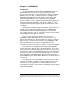
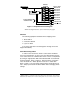
The 232D4SS8 has a Master port and eight selectable ports
labeled "A" through "H". Refer to “Rear View”. The Master port
should be connected to the RS-232 device that will be selecting the
ports. Ports "A - H” connect to the RS-232 or RS-422/485 devices
that will communicate with the Master port device.
Master Port
The Master port can be configured by the user as a DCE or a
DTE port. In order to determine the proper Master port
configuration of the 232D4SS8 it is necessary to have a basic
understanding of the terms DCE and DTE. RS-232 was designed,
using DB-25 connectors, for connecting a DTE (Data Terminal
Equipment) device to a DCE (Data Communication Equipment)
device. Each device will have inputs on pins that correspond to
outputs on the same pins of the other device. For example, a DTE
device transmits data out on pin 2 and a DCE device receives data
in on pin 2. IBM PC's are DTE devices, modems are DCE devices.
The Master port is shipped configured as a DCE port.
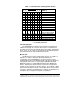
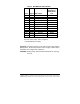
Table 1. Communication & Configuration Switch
DIP Switch 1
12 3456 78 Setting
0000XXXX300Baud
1000XXXX600Baud
0100XXXX1200 Baud
1100XXXX2400 Baud
0010XXXX4800 Baud
1010XXXX9600 Baud *
0110XXXX19.2KBaud
1110XXXX38.4KBaud
XXXX0XXX8DataBits*
XXXX1XXX7DataBits
XXXXX0XXSmartSwitchMode*
XXXXX1XXSmartSwitchand
Port Combiner Mode
XXXXXX0X3Char.Command*
XXXXXX1X4Char.Command
XXXXXXX0PortSelectTestOff*
XXXXXXX1PortSelectTestOn
0=OFF 1=ON X=DON'TCARE
* = FACTORY DEFAULT