
User Manual


Connector Pinouts
B-2 Appendix B Manual Documentation Number 3PCIoUx-1008
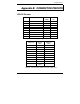
RS-422/485 Pinouts
Name Description Direction DB-9M
Pin
RD(A) −
Receive Data A Input 1
TD(B) + Transmit Data B Output 2
TD(A) −
Transmit Data A Output 3
GND Signal Ground ------ 5
RD(B) + Receive Data B Input 9
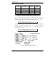
Figure 58. RS-422/485 Signal Designations and DB-9 Pinout
With 2-wire RS-485 mode operation, your connection cable must jumper
TD(A) to RD(A) and TD(B) to RD(B). Connect from TD(A) and TD(B) to
the Data A(−) and Data B(+) wires of your RS-485 network.
Note: Refer to Chapter 2 for example connections.
Note that the EIA RS-422 Specification labels data lines with an "A" and "B"
designator. Some RS-422 equipment uses a "−" and "+" designator. In almost
all cases, the "A" line is the equivalent of the "−" line and the "B" line is the
equivalent of the "+" line.
Note: For more information on RS-422 communications refer to the
B&B Electronics RS-422/485 Application Note at www.bb-elec.com
Figure 59. 2-Wire RS-485 Wiring Diagram