
Technical data


Operation ◆ Start Up
310633C 39
Start Up
1. Go through Checklist,
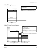
Mix Manifold Valve Settings
To open dispense or purge valves, turn their hex nut (E) counterclockwise. To close, turn clockwise. FIG. 41.
✓
Checklist
System grounded
Verify all grounding connections were made. See
Grounding, page 23.
All connections tight and correct
Verify all electrical, fluid, air, and system connec-
tions are tight and installed according to Installa-
tion instructions, page 12.
Fluid supply containers filled
Check component A and B and solvent supply
containers.
Mix manifold valves set
Check that mix manifold valves are set correctly.
Start with the settings recommended in Mix Mani-
fold Valve Settings, below, then adjust as
needed.
Packing nuts on dispense and purge
valves correctly torqued
Use a 3/8” or 10 mm wrench to torque the dis-
pense and purge valves packing nuts (D) to 25
in-lbs (2.8 N•m). F
IG. 41. Repeat this torque
weekly to extend valve life and avoid leakage.
Fluid supply valves open and pressure set
Component A and B fluid supply pressures should
be equal unless one component is more viscous
and requires a higher pressure setting.
Solenoid pressure set
75-100 psi inlet air supply (0.5-0.7 MPa, 5.2-7 bar)
Mix Manifold Valves
F
IG. 41
4A
4B
1B
1A
2B
2A
3B3A
D
Torque to 25 in-lbs
(2.8 N•m)
E
TI4608A
Valve Hex Nut (E) Setting Function
Dispense (3A, 3B) 1 turn out from fully closed Limits maximum fluid flow rate into integrator and
minimizes valve response time.
Purge (4A, 4B)
Fluid Shutoff (1A, 1B) Fully open during Run/Mix oper-
ation
Closes component A and B ports to integrator during
ratio check or meter calibration. Open ports during
Run/Mix operation.
Sampling (2A, 2B) Fully closed during Run/Mix
operation
Opens valves to dispense component A and B while
calibrating meters. Do not open sampling valves
unless fluid shutoff valves are closed.