The AZZA 810T Mainboard Series Cover Click Here Table Of Contents Click Here Introduction Click Here Hardware Installation Click Here BIOS Management Click Here R
8102T USER’S MANUAL Socket 370 AT Mainboard 8102T 810E2T Document NO: 8102ET-E1 Revision: 1.
User's Notice User’s Notice Copyright This publication contains information that is protected by copyright. No part of it may be reproduced in any form or by any means or used to make any transformation adaptation without prior written permission from the copyright holders. This publication is provided for informational purposes only.
Table Of Contents Chapter 1:- Introduction Page 5 1.1. Overview ................................................................................................... 5 1.1.1. Mainboard Series ................................................................................... 6 1.1.2. Mainboard Dimensions ........................................................................... 6 1.1.3. Environmental Limitations ...................................................................... 6 1.2.
Table Of Contents 2.7. Jumper Settings......................................................................................... 22 2.7.1. JP 1: OnNow Function ..............................................................................22 2.7.2. JP 2: Clear CMOS .....................................................................................23 2.7.3. JP 3: Clear Keyboard Password..................................................................23 Chapter 3:- Managing The PC BIOS Page 24 3.1. 3.2. 3.
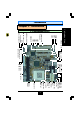
Introduction Chapter 1 - Introduction CN 21: CD-IN CN16: WOL PCI 1 PCI 2 PCI 3 2 1 4 3 JP3: Clear K/B Password USB USB USB USB CN 12: IR JP2: Clear CMOS CN 17: CPU Fan 2 LED 1 SPK (speaker) PWR LED/KBLOCK CN 3 : COM 1 CN 19: VGA System Panel and LED Connectors CN 4 : COM 2 CN 18: Game/ Audio CN 9 : IDE 1 CN 10: IDE 2 CN 8: FDC CN 2: M/S CN 1: K/B JP1: OnNow Function CN 15: ATX Power Connector CN 14: AT Power Connector CN 13: CPU Fan 1 CN 5: LPT Socket 370 DIMM 1 DIMM 2 5 Introduction 1.
Introduction Introduction 1.1.1. Mainboard Series The 810 mainboard series has two models. They are: 1. 8102T 2. 810E2T 1.1.2. Mainboard Dimensions Width & Length: Height: PCB Thickness: Weight: 1.1.3. 222 mm x 210 mm. 1 1/2 inches 1.6 mm 18 ounces. 8.27 inches x 8.74 inches Environmental Limitations Operating Temperature: Required Airflow: Storage Temperature: Humidity: Altitude: 10°C to 40°C . (50°Fto 104°F) 50 linear feet per minute across CPU. - 40°C to 70°C.
Introduction Expansion Slots Onboard Audio Features • Supports Microsoft ® DirectSound/DirectSound 3D. • AC97 supported full duplex, independent sample rate converter for audio recording and playback. Front Audio Port (Optional) For use with a Front Utility Panel that connects Ear Phone, Microphone and Audioin. For more details, please consult your dealer. Word Size Data Path: Address Path: 8-bit, 16-bit, 32-bit, 64-bit. 32-bit. FRONT SIDE BUS FREQUENCY Supports 66 MHz, 100 MHz and 133 MHz FSB.
Introduction WOL (Wake-On-Lan) Port (optional) Introduction One WOL connector supports Wake-On-LAN functionality. USB Ports The mainboard is equipped with four internal USB connectors. USB allows data exchange between your computer and a wide range of simultaneously accessible external Plug and Play peripherals. ( Cable set for two connectors are optional and is sold separately).
Introduction 1.3 Intelligence Management Setup, this switch allows the system to enter the Soft-Off or Suspend mode. External Modem Ring-on (optional) The Modem Ring-on feature allows the system that is in the Suspend mode or Soft Power Off mode to wake-up/power-on to respond to incoming calls. This feature supports external modem only. RTC Timer to Power-on the System The RTC installed on the system board allows your system to automatically power-on on the set date and time.
Hardware Installation Chapter 2 - Hardware 2.1. Installation Check List The following is a checklist of all the expansion slots, jumpers and connectors that should be configured on your mainboard before you can run your pc. Installation Checklist Expansion Slots and Sockets Hardware Installation CPU Slot DIMM Slots PCI Slots Socket 370 supports Celeron, Pentium III and Cyrix C3. Two 168 pin slots that support upto 512 MB SDRAM. Three 32 bit PCI Slots.
Hardware Installation Installation Checklist (Continued) System Panel Buttons and LED Connectors PW TL HL RS Power On/Off and Suspend Switch Connector.
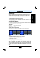
1 CN 7: USB2 1 CN 16: WOL PCI 2 1 1 PCI 1 1 1 JP2: Clear CMOS CN 17: CPU FAN2 1 1 CN 21: CD Audioo In CN 22: CD Audio In CN 18: Game/Audio CN 3: COM1 CN 5: LPT CN 19: VGA CN 2: MS CN 4: COM2 CN 10: IDE 2 CN 9: IDE 1 1 1 1 1 CN 1: K/B JP1: K/B PWR CN 14: AT Power Supply CN 15: ATX Power Supply 1 DIMM 2 DIMM 1 CN 13: CPU FAN1 CN 8: FDC 12 JP3: Clear K/B Password CN 12:I R CN 6: USB1 1 CN 30: USB3 PCI 3 1 CN 31: USB4 1 System Panel Buttons and LED Connectors PWR-LED/KBLOCK SPK 1 H
Hardware Installation 2.3. CPU, Memory and Expansion Slots 2.3.1 Installation of Processor (CPU) Before you install the processor, make sure that you have an approved Heat Sink with Cooling Fan. Without proper heat sink with cooling fan will damage the processor and mainboard. To install your processor, please do the following: 1. Locate a small dot marked on top of the CPU. The marking indicate Pin 1 of the CPU. 2. Locate the Socket Pin 1 marking on the mainboard. 3.
Hardware Installation NOTE: “Out Of Memory” Error Message If you have installed more than 512 MB of RAM and are running Microsoft Windows Millennium Edition, Windows 98 Second Edition, Windows 98 or Windows 95 you may experience memory problems. Two symptoms of these problems are being unable to run an MS-DOS session while you are running Windows or the computer may stop responding while Windows is starting.
Hardware Installation 1 2 3 4 5 2.4.2 PS/2 Mouse Connector Connector: CN2 Type: 5 pin Mouse Data No Connection Ground +5V DC Mouse Clock This mainboard comes with a single PS/2 mouse connector. Use the ribbon cable that has been provided to connect your PS/2 Mouse Connector mouse. 2.4.3 Serial Port Connectors: COM1 and COM2 PIN 1 Connector: CN3 (COM1) / CN4 (COM2) Type: 9 pin Serial Port Connector PIN 1 2.4.
Hardware Installation 2.4.6. Floppy Disk Drive (FDC) Connector: CN 8 Type: 34 pin block The FDC connector can support two Floppy drives. It is located at the front of the mainboard. To connect, use the ribbon-cable that has been provided. Make sure that the red strip is connected to PIN 1 of the connector. Top View of a Floppy Disk Drive PIN 1 17 PINS Hardware Installation 2.4.7.
Hardware Installation Hardware Installation 2.4.9. CPU Fan and Chassis Fan Connector Connector: Type: CN 13 (CPU Fan 1)/CN 17 (Chassis Fan) 3 pin The cooling fans must be connected to their respective power connectors. Top View of a Fan Connector 1 Ground 2 3 +12V DC Fan Signal Front View of a Fan Connector +12V DC Fan Signal Ground Connector: Type: CN 14 12 pin block This must be connected to an AT power supply. The plug from the power supply can only be inserted in one orientation.
Hardware Installation 2.4.12. WOL (Wake On LAN) Connector(Optional) Connector: Type: CN 16 (WOL) 3 pin The WOL connector must be connected to a LAN card that has Wake-On-LAN (WOL) output. This connector powers up the system when a wakeup packet or signal is received through the LAN card.
Hardware Installation 2.4.15. CD Audio-in Connector Connector: Type: CN 21 (un-housed) 4 pin Top View of an Un-housed Front View of an Un-housed CD-Audio In CD-Audio In Connector. Connector. Left Channel Audio In 2 Ground 3 Ground 4 Right Channel Audio In Right Channel Audio In 2.4.16. Connector: Type: Ground Left Channel Audio In AIR Bus Connector (Optional) PIN 1 CN 25 15 pin AIR Bus is a revolutionary technological development. It is used in conjunction with Portable BIOS.
Hardware Installation PIN 2: MIC-IN PIN 4: No Connection PIN 6: LINE-IN Left PIN 8: EARPHONE Left PIN 10: Ground PIN 1: Ground PIN 3: MIC_RCH PIN 5: LINE-IN Right PIN 7: Ground PIN 9: Earphones Right Top View of the Front Audio Connector 2. 2.5 5. System Panel Buttons and LED Connectors Hardware Installation PIN 1 PIN 2 Ground The following System Panel Buttons and LED PW:+5V DC Pull Up Connectors can be found at the front of the No Connection mainboard on the left hand side.
Hardware Installation Mode 2: Press and hold the Power ON button for more than 4 seconds, the system will be completely powered off. Option 2: If you choose “Instant OFF.” In the BIOS CMOS Setup, the power switch will operate like a normal ON / OFF Power button. 2.5.2. TL: Turbo LED When you push the Turbo button on the front of your Chassis, this LED will come on. 2.5.3. HL: IDE HDD LED Connector Any read and write activity by the HDD will turn this LED on.
Hardware Installation 2.7. Jumper Settings Jumpers are built on the mainboard to allow the user flexibility to configure the mainboard settings to meet their specific requirements. The 810T mainboard series come with three jumpers. All the jumpers have three 3-pins. When there is a jumper cap inserted on pins 1 and 2 we say PIN 1 and PIN 2 are SHORT. When the jumper cap is inserted on pin 2 and 3, we say PIN 2 and PIN 3 are SHORT (see the diagram below).
Hardware Installation 2.7.2. JP2: Clear CMOS Default: PIN 1 and PIN 2 Short (Normal) Short: PIN 1— PIN 2 Short: PIN 2— PIN 3 Normal Clear CMOS Data If you have made an improper setting in the BIOS setup and your computer is not functioning, or if you have forgotten your password, you can use this jumper, JP2, to clear the CMOS memory and to reconfigure your system. 2.7.3.
BIOS Setup Chapter 3 - Managing the PC BIOS 3.1. Award BIOS CMOS Setup Utility The EEPROM on the mainboard stores the AWARD BIOS CMOS Setup Utility to allow you to configure your system. Anytime, you wish to configure your system BIOS, you need to run BIOS CMOS Setup Utility (for example, you may wish to set the Security Password System or changing your Power Management Setting).
BIOS Setup 3.
BIOS Setup 3.3. STANDARD CMOS SETUP CMOS Setup Utility - Copyright ( C ) 1984 - 2001 Award Software. Standard CMOS Setup Date (mm : dd : yy) : Tue, July 24 2001 Item Help Time (hh : mm : ss) : 14 : 52 : 45 !IDE Primary Master [Maxtor 2049H4] !IDE Primary Slave [None] !IDE Secondary [None] !IDE Secondary [None] Drive A [1.44, 3.5 in.
BIOS Setup CYLS. HEADS PRECOMP LANDZONE SECTORS Number of cylinders Number of heads Write precomp Landing zone Number of sectors The information should be provided in the documentation form your hard disk vendor or the system manufacturer. If a hard disk has not been installed select NONE and press . Drive A /B: Select the correct specifications for the diskette drive(s) installed in the computer. None 360K, 5.
BIOS Setup Base Memory Extended Memory Total Memory 3.4. : Indicates the memory installed below the conventional 1MB space. : Indicates the memory installed above the 1MB space. : Indicates the total memory installed in the PC system.
BIOS Setup Virus Warning When enabled, you receive a warning message if a program (specifically, a virus) attempts to write to the boot sector or the partition table of the hard disk drive. You should then run an anti-virus program. Keep in mind that this feature protects only the boot sector, not the entire hard drive. Many disk diagnostic programs that access the boot sector table can trigger the virus-warning message.
BIOS Setup Boot Up Floppy Seek When enabled, the BIOS tests (seeks) floppy drives to determine whether they have 40 or 80 tracks. Only 360-KB floppy drives have 40 tracks; drives with 720 KB, 1.2 MB, and 1.44 MB capacity all have 80 tracks. Because very few modern PCs have 40-track floppy drives, we recommend that you set this field to Disabled to save time. Boot Up NumLock Status Toggle between On or Off to controls the state of the NumLock key when the system boots.
BIOS Setup PS/2 mouse function control This mainboard has a built-in PS/2™ mouse port. If you are using the PS/2™ mouse, please leave this field as “Enabled”. In case you prefer to connect a serial mouse to the serial port instead of using the PS/2™ mouse, you may choose “Disable” in this field so that the IRQ12 can be released for other devices. OS Select For DRAM > 64MB Select OS2 only if you are running OS/2 operating system with greater than 64 MB of RAM on your system.
BIOS Setup CMOS Setup Utility—Copyright © 1984—2001 Award Software Advanced Chipset Features SDRAM CAS Latency [3] Item Help SDRAM Cycle Time Tras/Trc [6/8] Menu Level SDRAM RAS - to - CAS Delay [3] SDRAM RAS Precharge Time [3] System BIOS Cacheable [Disabled] Video BIOS Cacheable [Disabled] Memory Hole At 15M - 16M [Disabled] CPU Latency Timer [Disabled] Delayed Transaction [Enabled] On-Chip Video Window Size [64MB] Video BIOS Cacheable Selecting Enabled allows caching of the video BI
BIOS Setup memory to store 3D texture mapping data to increase the video display performance. The field allows you to define the memory size which you prefer to use for the AGP Port. The memory size selectable is either "Disable" or 32MB or 64MB DVMT. When you select 64MB DVMT, it allows the maximum 64 MB memory which Windows 95/98 can use to store the 3D texture. When you select the 64MB DVMT, you will see 1024K memory is allocated as the shared memory when you power on the PC system.
BIOS Setup BIOS CMOS Setup Utility - Copyright (C) 1984 - 2000 Award Software Integrated Peripherals On-Chip Primary PCI IDE [Enabled] On-Chip Secondary PCI IDE [Enabled] IDE Primary Master PIO [Auto] IDE Primary Slave PIO [Auto] IDE Secondary Master PIO [Auto] IDE Secondary Slave PIO [Auto] IDE Primary Master UDMA [Auto] IDE Primary Slave UDMA [Auto] IDE Secondary Master UDMA [Auto] IDE Secondary Slave UDMA [Auto] USB Controller [Enabled] USB Keyboard Support [Disabled] Init Display first [PCI Slot] AC97
BIOS Setup AC97 Audio There is the Audio interface built in the system chipset. You can use this field to configure the onboard Audio interface or disable the audio interface. AC97 Modem Set this field to “Auto” if you installed a CNR Modem card. IDE HDD Block Mode This selection allows your hard disk controller to select the block mode to transfer data to and from your hard disk drive (HDD). Enabled IDE controller uses block mode. Disabled IDE controller uses standard mode.
BIOS Setup UART Mode Select This field allows you to determine the mode of the UART port. RxD, TxD Active This item allows you to determine the active of RxD, TxD IR Transmission delay This item allows you to enable/disable IR transmission delay. UR2 Duplex Mode This item allows you to select the IR half or full duplex function. Use IR Pins This item allows you to select IR transmission routes, one is RxD2m, TxD2 (COM Port 2) and the other is IR-Rx2Tx2 (CN12).
BIOS Setup 3.
BIOS Setup According to what was defined by the ACPI in Windows 98, the PW switch can be either the "Standby switch" or "shutdown switch". When "Standby switch" is selected, the first click on the PW switch will have the PC system turn into standby mode. If you want to "wake up" the PC system, you will have to use the devices (such as keyboard, mouse ..
BIOS Setup Blank Screen This selection will cause the system to turn off the vertical and horizontal synchronization ports and write blanks to the video buffer. This option only writes blanks to the video buffer. DPMS Initial display power management signaling. V/H SYNC+Blank Video Off In Suspend When you select Yes, the screen display will be disabled ( no display on the screen) when the PC system is in the suspend mode.
BIOS Setup Power On by Ring / LAN When “Enabled”, you can use the Modem Ring signal or the LAN wake up signal to power on the PC system. CPU Thermal Thermal--Throttling This field allows you the select the CPU throttle rate. When CPU temperature is too high, the onboard hardware monitoring will tell the CPU to reduce to the throttling speed to protect the CPU. The choice available for the CPU throttling rate are: 12.5%, 25.0%, 37.5%, 50.0%, 62.5%, 75.0%, 87.5%.
BIOS Setup CMOS Setup Utility - Copyright (C) 1984 - 2001 Award Software PnP/PCI Configuration PNP OS Installed [No] Item Help Reset [Disabled] Menu Level" ""! Configuration Resources Controlled [Auto (ESCD)] X IRQ Resources Press Enter X DMA Resources Press Enter X Memory Resources Press Enter PCI/VGA [Disabled] Palette Default is Disabled.
BIOS Setup 3.9 Frequency/Voltage Control CMOS Setup Utility - Copyright (C) 1984 - 2000 Award Software Frequency/Voltage Control Auto Detect DIMM/PCI Clk [Disabled] Item Help Spread Spectrum [Disabled] Menu Level CPU Host /SDRAM Clock [66] CPU Clock Ratio [X 3] Auto Detect DIMM/PCI Clk When “Enabled”, it will auto detect the devices presences on DIMM and PCI slots.
BIOS Setup 3.
BIOS Setup The “SUPERVISOR PASSWORD” is for you to control unauthorized access to your BIOS CMOS Setup or Booting into the your PC system. The Supervisor Password option is used together with the Security Option in section. When "Setup" is selected in Security Option: If you want to change the BIOS setting, you will have to key-in the Supervisor Password so that you can start the BIOS CMOS Setup Utility and change the system setting.
BIOS Setup 2. When "System" is selected in Security Option: When you turn on the PC system, it will request you to enter the Password. Without the correct password, PC system will stop and the operating system won't be loaded. B. When there is no password stored in the "SUPERVISOR PASSWORD" 1. When "Setup" is selected in Security Option: Users can use the "User Password" to log into the BIOS setup program, and they can make all the change in the BIOS setup program. 2.