
Data Sheet


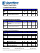


Table Of Contents

14
FORM NO.: FR2-015_ A Responsible Department:WBU Expiry Date: Forever
The information contained herein is the exclusive property of AzureWave and shall not be distributed, reproduced, or disclosed
in whole or in part without prior written permission of AzureWave.
3. Electrical Characteristics
3.1 Absolute Maximum Ratings
Symbol
Parameter
Minimum
Typical
Maximum
Unit
VBAT
DC supply for the VBAT and PA driver
supply
-0.5
-
+6.0
V
VDDIO
DC supply voltage for digital I/O
-0.5
-
+3.9
V
3.2 Recommended Operating Conditions
Symbol
Parameter
Minimum
Typical
Maximum
Unit
VBAT
Power supply for the internal regulators
and FEM
3.2
3.6
4.8
V
VDDIO
DC supply voltage for digital I/O
1.71
-
+3.63
V
3.3 Digital IO Pin DC Characteristics
Symbol
Parameter
Minimum
Typical
Maximum
Unit
VDDIO=1.8V
VIH
Input high voltage (VDDIO)
1.17
-
-
V
VIL
Input low voltage (VDDIO)
-
-
0.63
V
VOH
Output High Voltage @ 2mA
1.35
-
-
V
VOL
Output Low Voltage @ 2mA
-
-
0.45
V
VDDIO=3.3V
VIH
Input high voltage (V
DDIO
)
2.0
-
-
V
VIL
Input low voltage (V
DDIO
)
-
-
0.8
V
VOH
Output High Voltage @ 2mA
2.9
-
-
V
VOL
Output Low Voltage @ 2mA
-
-
0.4
V