AW-GE870 802.
COPYRIGHT AzureWave Technologies, Inc. All rights reserved. No part of this document may be reproduced, transmitted, transcribed, stored in a retrieval system, or translated into any language in any form or by any means without the written permission of AzureWave Technologies, Inc. DISCLAIMER AzureWave provides this document “as is”, without warranty of any kind, neither expressed nor implied, including, but not limited to, the particular purpose.
Contents Safety statements.......................................................................................................... 2-1 About this guide ............................................................................................................ 2-1 AW-GA800BT802.11 b/g PCI Express WLAN Card specification summary............................ 2-2 Chapter 1 Product Information...................................................................................... 2-2 1.1 Product overview........
Safety statements FCC Radiation Exposure Statement: This equipment complies with FCC radiation exposure limits set forth for an uncontrolled environment. This transmitter must not be co-located or operating in conjunction with any other antenna or transmitter. About this guide The user guide contains the information you need to install and configure your AzureWave802.11 b/g PCI Express WLAN Card.
AzureWave802.11 b/g PCI Express WLAN Card specification summary Host system connections Interface Chapter 1 1.1 Fully complies with PCI Express 1.0a interface. Product Information Product overview Thank you for choosing AzureWave802.11 b/g PCI Express WLAN Card. The AzureWave802.11 b/g PCI Express WLAN Card is an easy-to-use wireless local area network (WLAN) adapter which is designed for home or office use.
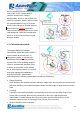
requiring manual installation. Make sure that your system meets the following requirements. z z z z motherboard with PCI Express Card Slot Minimum 64MB system memory Operating system Station mode : Windows® 2000/XP/Server 2003, Windows XP/Server 2003 x64 AP/wireless bridge mode : Windows® 2000/XP/Server 2003 Optical drive for utilities and driver installation Easy hardware installation Please plug AzureWave802.11 b/g PCI Express WLAN Card in motherboards lot PCI-E x1.
Ad-Hoc wireless networks bring together workstations and computers to act as servers to all other users on the network without complex infrastructure, setup or administration. Users on the network can share files, printers. When in ad hoc mode, the AzureWave802.11 b/g PCI Express WLAN Card connects to another wireless device within its effective range and communicates with each other in the same LAN workgroup. Select this configuration when no access point is present in your wireless network. 1.3.
Access point establishes the bridge between wireless LAN and other wired counterparts. You could configure AzureWave802.11 b/g PCI Express WLAN Card as a software access point (soft AP). In this mode, the AzureWave802.11 b/g PCI Express WLAN Card acts as the access point that provides wireless links in the validating range to client stations to the internet.
Chapter 2 2.1 Installation System requirements Before installing the AzureWave802.
Chapter 3 3.1 WiFi-AP Solo Wizard Launch WiFi-AP Solo Wizard In this section, you will obtain detail instruction in setting wireless configuration by following WiFi-AP Solo Wizard. Please refer to Chapter 1.4 to understand the network types the AzureWave802.11 b/g PCI Express WLAN Card supports. In the first time installation, WiFi-AP Solo Wizard is executed immediately after installation to help you set the proper wireless configuration.
3.2 Wi-Setup Wizard Steps Whatever which wireless configuration you would set up, the first scene of WiFi-AP Solo Wizard is “Select Operation Mode” dialog that shows as right picture. You could select either station or AP mode from the first step. For Ad-hoc and infrastructure type configuration, you should select Station mode. The software access point configuration could be archived by select AP mode. z Station Set the operation mode to be “Station”. Follow steps in section 4.3.
Give up WiFi-AP Solo Wizard and keep the last configuration. 3.3.1 Configure Infrastructure type network It is easy to build up infrastructure type network with WiFi-AP Solo Wizard. The next step after select infrastructure type network is to select the desired connection. Select the BSS connection list Select valid wireless BSS, Infrastructure Basic Service Set, connection nearby your system for connecting. The listed BSS are touchable access point around you.
z Cancel Give up WiFi-AP Solo Wizard and keep the last configuration. Setup TCP/IP You have to setup the TCP/IP by following the configuration of connect access point. The following setting should match the configuration of access point you join. Please check the setting of it. z Back Go back to previous step ~ Select the IBSS connection list z Finish All settings of infrastructure are finished. 3.3.
z New IBSS Create a new Ad-Hoc station by the shown-up dialog instead of joining with a present Ad-Hoc node. In this dialog, you could configure network name, applied channel, authentication and encryption rule on this Ad-Hoc node. After creating a new Ad-Hoc node, the steps of build Ad-Hoc network connection is finished. z Refresh Rescan the Ad-Hoc stations nearby this system. z Back Go back to previous step ~ Select Station Type. z Next The wizard will show up the contents of profile.
Only basic settings are included in following steps. Less-experience users could apply this kind setup to archive access point setup. Fundamental security setting is included. z Back Go back to previous step ~ Select Operation Mode z Next The next step is dependant on the option user select: z Cancel Give up current WiFi-AP Solo Wizard setup and roll back to previous configuration. 3.4.
and connect to internet. z Cancel Give up current WiFi-AP Solo Wizard setup and roll back to previous configuration. Wireless Network Security Two types pass key, ASCII and Passphrase, perform security with different level. z ASCII You should provide either 5 or 8 ASCII characters on Network key edit box. z PASSPHRASE You could input words on Network Key edit box. 64 bits: The generated pass key is 64-bits to be company with data packets.
z Next Confirm the current setting and go to next step ~ Finish. z Cancel Give up current WiFi-AP Solo Wizard setup and roll back to previous configuration. Select the Internet Connection List This step only shows with multiple network connection system. If there is only one internet connection available, this step is discarded. In this step, you have to select one network connection from the list box. This network connection should be configured to connect internet.
Finish z Finish Press finish button to close WiFi-AP Solo Wizard. The wireless configuration is going to be applied within few seconds. 3.4.2 Advanced User The steps of advanced user provide more detail configuration including channel and authentication Wireless Network Properties In this step, you could assign the channel number and authentication mode for the access point. If the setting of WEP to be “Disable” and Authentication to be “Open system”, then this access point is opened for free join.
z WEP Encryption An encryption system prevents eavesdropping on wireless network traffic. Enable: The joined wireless station should have same network/password key with this access point. z Disable: no network/password key is required for joined wireless station. Authentication The next generation of Wi-Fi security, Wi-Fi Protected Access, or WPA, will use authentication to verify whether users have access to a particular wireless network.
Go back to previous step ~ Wireless Network Properties z Next Go to next step ~ Show Setting Information Cancel Give up current WiFi-AP Solo Wizard setup and roll back to previous configuration. z Show Setting Information z Back If you do not satisfy with current setting, you could go back to previous step ~ Wireless Network Security z Next Confirm the current setting and go to next step ~ Finish. z Cancel Give up current WiFi-AP Solo Wizard setup and roll back to previous configuration.
z Cancel Give up current WiFi-AP Solo Wizard setup and roll back to previous configuration. Finish z Finish Press finish button to close WiFi-AP Solo Wizard. The wireless configuration is going to be applied within few seconds.
Chapter 4 Wireless LAN Management GUI 4-1
4-2
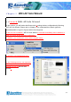
4.1 How to Launch AzurewaveWLAN You could launch AzurewaveWLAN from either Windows® Program Menu or tray icon. The tray icon is an optional quick launch to be enabled by user. Windows® Program Menu It is the absolute way to launch AzurewaveWLAN from program folder. Tray Icon The tray icon will not be show until you enable the “Show Tray Icon” from AzurewaveWLAN as the right picture. As the AzurewaveWLAN icon shown on system tray, you could double click the icon with mouse button to launch it. 4.
Main Menu The main menu includes five submenus. z Refresh As clicking the refresh menu, the contents of adapter list area are re-enumerated and updated. z Set up Wizard Quickly launching the WiFi-AP Solo Wizard. The convenient quick launching helps you to reprogram the wireless configuration as need.
z Adapter List Area This area displays all connected adapters on this system for mutiple adatper installations. The easy switch helps user to change the selected adapter by one click. The contents of properties area are dependant on wireless configuration that the selected adapter was set up. For single adatper installed system, the only one adapter is always selected. z Properties Area The contents of this area are dependent on current wireless configuration.
z Global Control Bar Each control items on this bar affects the adapter or management GUI directly. Show Tray Icon Making this item to be checked, the management GUI will minimize and stay on the tray icon located at the right down corner of Windows while pressing “Close” button. In other word, management GUI will shut down while pressing “Close” button with unchecked condition.
4.3.1 Infrastructure and Ad-Hoc With both Infrastructure and Ad-Hoc types, the properties should looks like the picture beside. Six property pages present different information of current wireless network status. Reading the following explanations before you reviewing these pages, it could help you to well know the wireless environment around the system.
z Network Address group Mac Address: six two-digital number of this adapter IP Address: assigned network address by DHCP server or self-definition in four three-digital number format Subnet Mask: the only valid value is 2555.255.255.0 Gateway: It comes from connected access point. Your system can not connect internet with this field empty. Profile page This page provides profiles management like add, remove, edit and duplicate just by pressing the button.
Create profile for selected network connection in profile list and add it in to profile list. Advanced page z Power Save None: without power save mode Min: wake up every two time interval to receive packets Max: wake up every ten time interval to receive packets z z Wireless Mode 802.11b 802.11g/b 802.11b Preamble Mode Long: higher quality but with lower performance than preamble short mode Short: Normal quality but with higher performance then preamble long mode.
Status page z z z z z z z z z z z z z z z z Manufacturer: It always is Atheros. NDIS Driver Version: Short Radio Header Encryption: Current encryption mode. Authenticate: authentication state Channel Set: selected channel plan currently. Please reference Appendix-A with the detail comparisons. MAC Address: MAC address of this adapter.
4.4 AP mode General Page In this page, it provides general information of this access point including name, MAC address and list of joined stations. z SSID The name of this access point is. z BSSID Six two-digital numbers configure the MAC address of this access point. z Association Table It is the list of joined station on this access point. AID (Association ID) The AID field is a value assigned by an AP during association that represents 16-bit ID of a station.
Three types authentication: Open System It is combined with data encryption type to be WEP or disable. Encryption ~ disabled: you decide to open this access point to every one without network authentication. Encryption ~ WEP: you decide to setup the basic data encryption with a defined network key. Shared Key + WEP You decide to apply both authentication and data encryption to prevent illegal login.
z Preamble Mode Long: higher quality but with lower performance than preamble short mode Short: Normal quality but with higher performance then preamble long mode. Auto: select the proper preamble mode by current signal frame information. Statistics Page You could watch the Tx/Rx status of current wireless connection. It provides a statistic analysis of packet transition. SoftAP Page z ConnName list box List all network connections on this system.
4.5 Windows Zero Configuration The Windows Zero Configuration is a wireless LAN service that does not provided by Microsoft Windows® until Windows XP. It provides basic and easy on connecting the wireless network. In this chapter, we introduce you the steps to swap between Windows Zero Configuration and AzurewaveWLAN. If you prefer Windows Zero Configuration instead through AzurewaveWLAN, then you should follow the steps in 4.5.1 to switch to Windows Zero Configuration.
After opening the page of present wireless network, if you see the scene similar to the following figure, then you had been swapped to Windows Zero Configuration successfully. Otherwise, you should check and repeat the previous steps again. 4.5.2 Rollback from Windows Zero Configuration to AzurewaveWLAN If you prefer the AzurewaveWLAN instead of Microsoft® Windows Zero Config, please follow the steps to rollback.
4-16
Appendix A: Mapping of country and channel plan Channels 1~11 Country Argentina ,Brazil ,Canada ,Colombia ,Mexico ,Taiwan ,United States of America,Yugoslavia Channel Set FCC,IC,TAIWAN Australia ,Austria ,Bahrain ,Belarus ,Belgium ,Bolivia ,Bulgaria ,Chile ,China ,Co sta Rica ,Croatia ,Cyprus ,Czech Republic,Denmark ,Egypt ,Estonia ,Finland ,France2 ,Germany ,Greece ,Hong Kong,Hungary ,Iceland ,India ,Indonesia ,Ireland ,Italy ,Kuwait ,Latvia ,Lebanon , Liechenstein ,Lithuania ,Luxembourg ,Macedonia, T
Appendix B: Q&A Q: After applying security setting, why my computer can not connect to the system that configures the AzureWave802.11 b/g PCI Express WLAN Card as AP mode? A: There are several condition could result this issue. z z Security setting mismatch: please make sure the security and network key are identical to both AP and station side. Station utilizes Windows Zero Configuration to join the Access Point: you could change the WEP to be ASCII or Hexadecimal.
Appendix C: Release History Version Comments Opposite Package Version 1.2 Update ICS operation of user interface 10.27 ~ Add Appendix C for release history 1.1 Update Windows Zero Configuration operations of user interface 10.27 ~ 1.0 First formal release 09.
Federal Communication Commission Interference Statement This equipment has been tested and found to comply with the limits for a Class B digital device, pursuant to Part 15 of the FCC Rules. These limits are designed to provide reasonable protection against harmful interference in a residential installation. This equipment generates, uses and can radiate radio frequency energy and, if not installed and used in accordance with the instructions, may cause harmful interference to radio communications.
Industry Canada Statement This device has been designed to operate with an antenna having a maximum gain of 3 dBi. Antenna having a higher gain is strictly prohibited per regulations of Industry Canada. The required antenna impedance is 50 ohms. To reduce potential radio interference to other users, the antenna type and its gain should be so chosen that the EIRP is not more than required for successful communication.
DGT 警語 : 經型式認證合格之低功率射頻電機,非經許可,公司、商號或使用者均不得擅自變更頻率、加大 功率或變更原設計之特性及功能。 低功率射頻電機之使用不得影響飛航安全及干擾合法通信;經發現有干擾現象時,應立即停用, 並改善至無干擾時方得繼續使用。前項合法通信,指依電信法規定作業之無線電通信。低功率射 頻電機須忍受合法通信或工業、科學及醫療用電波輻射性電機設備之干擾。 4-7