ADSL2+ Ethernet USB Combo Router - User Guide Page 1 of 67
ADSL2+ Ethernet USB Combo Router - User Guide Table of Contents Preliminary Pages Page Table of Contents............................................................................................................. 2 List of Illustrations .......................................................................................................... 5 Chapter 1 - About this Manual ...................................................................................... 9 1.1 Introduction .........................
ADSL2+ Ethernet USB Combo Router - User Guide 4.5.11 TR-068 WAN Access ................................................................. 32 4.5.12 DNS Proxy.................................................................................. 33 4.5.13 Dynamic DNS Client .................................................................. 34 4.5.14 Port Forwarding .......................................................................... 35 4.5.15 Bridge Filters .........................................
ADSL2+ Ethernet USB Combo Router - User Guide 4.7.9 Product Information .................................................................... 66 4.8 Help ............................................................................................
ADSL2+ Ethernet USB Combo Router - User Guide List of Illustrations Figure Page Figure 1-1 : ADSL Router Configuration Diagram .......................................................... 10 Figure 1-2 : Front Panel Indicators (For Ethernet USB Combo Router) ........................... 12 Figure 1-3 : Back Panel Indicators (For Ethernet USB Combo Router)............................ 13 Figure 1-4 : Quick Start ..................................................................................................
ADSL2+ Ethernet USB Combo Router - User Guide Figure 1-25 : Port Forwarding ......................................................................................... 35 Figure 1-26 : Bridge Filters ............................................................................................. 36 Figure 1-27 : Web Access Control................................................................................... 37 Figure 1-28 : No Egress..........................................................................
ADSL2+ Ethernet USB Combo Router - User Guide Figure 1-53 : DDNS Update Status.................................................................................. 64 Figure 1-54 : DDNS Status (DDNS Client Enabled) ........................................................ 64 Figure 1-55 : DHCP Clients............................................................................................. 65 Figure 1-56 : QoS Status............................................................................................
ADSL2+ Ethernet USB Combo Router - User Guide Safety Summary Messages WARNING HIGH VOLTAGE is used in the equipment. Make sure equipment is properly grounded BEFORE opening. Failure to observe safety precautions may result in electric shock to user. CAUTION Check voltages before connecting equipment to power supplies. Wrong voltages applied may result in damage to equipment.
ADSL2+ Ethernet USB Combo Router - User Guide Chapter 1 - About this Manual 1.1 Introduction This manual provides a general product overview and description of its subsystems and components and basic operation and preventive maintenance instructions of the ADSL2+ Ethernet & USB Combo Router. 1.
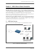
ADSL2+ Ethernet USB Combo Router - User Guide Chapter 2 – ADSL Ethernet Router Description The ADSL2+ Ethernet & USB Combo Router is the perfect high-speed WAN bridge/router. This full-featured product is specifically designed to connect to the Internet and directly connect to your local area network via high speed 10/100 Mbps Ethernet. The ADSL Router has also full NAT firewall and DMZ services to block unwanted users from accessing your network.
ADSL2+ Ethernet USB Combo Router - User Guide Chapter 3 - Your Gateway At A Glance The ADSL2+ Ethernet & USB Combo may have different ports and LEDs. Let’s take a look at the different options. Depending on your model, it may have some or all of the features listed below. 3.1 Ports and Buttons Reset and Restore to Factory Defaults: The restore to factory defaults feature will set the ADSL Router to its factory default configuration by resetting the ADSL Router.
ADSL2+ Ethernet USB Combo Router - User Guide 3.2 ADSL Router Overview 3.2.1 Front Indicators Figure 1-2 shows the front indicators of the ADSL Router. 2 1 3 4 5 Figure 1-2 : Front Panel Indicators (For Ethernet USB Combo Router) LED Name Status & Meaning 1 PPP Lights up when the PPP connection is established. 2 PWR Lights up when power is supplied to the Router. 3 DSL Lights up when the ADSL connection is established.
ADSL2+ Ethernet USB Combo Router - User Guide 3.2.2 Back Panel Figure 1-3 shows the back panel indicators of the ADSL Router. 2 1 4 3 5 Figure 1-3 : Back Panel Indicators (For Ethernet USB Combo Router) Label Description 1 DSL Telephone jack (RJ-11) to connect to your Telephone Wall Socket (ADSL line). 2 USB USB Port to connect to the USB port on your Computer/Notebook.
ADSL2+ Ethernet USB Combo Router - User Guide Chapter 4 - Setting Up the ADSL Router This section will guide you through your ADSL Router’s configuration. The ADSL Router is shipped with a standard PPP configuration. The basic tabs consist of features which are catered for basic users. 4.1 Logging into your ADSL Router To configure your ADSL Router, open your web browser. You may get an error message at this point; this is normal. Type the default IP address (10.0.0.138) on the web address bar.
ADSL2+ Ethernet USB Combo Router - User Guide For those who have their routers configured, you will be directed to the “Basic Home” page. See Figure 1-5. Figure 1-5 : Basic Home 4.2 Quick Start If you have already configured your router and wish to change your current configuration, click on the ‘Quick Start’ link. Figure 1-6 will appear.
ADSL2+ Ethernet USB Combo Router - User Guide 4.3 LAN / DHCP Configuration On one side of your ADSL Router, you have your own Local Area Network (LAN) connections. This is where you plug in your local computers to the ADSL Router. The ADSL Router is normally configured to automatically provide all the PC's on your network with Internet addresses. To enable or disable DHCP, click Basic, then select LAN Configuration. The Start IP Address is where the DHCP server starts issuing IP addresses.
ADSL2+ Ethernet USB Combo Router - User Guide Figure 1-7 : LAN / DHCP Configuration Page 17 of 67
ADSL2+ Ethernet USB Combo Router - User Guide 4.4 Diagnostic Test Diagnostic Test is used for investigating whether the ADSL Router is properly connected to the WAN Network. See Figure 1-8. This test may take a few seconds to complete. To perform the test, select your connection from the list and press the Test button. Before running this test, make sure you have a valid DSL link.
ADSL2+ Ethernet USB Combo Router - User Guide 4.4.1 Ping Test Once you have your ADSL Router configured, ensure you can ping the network. Type the target address that you want to ping. If your PC is connected to the ADSL Router via the default DHCP configuration, you should be able to ping the network address 192.168.1.1. See Figure 1-10. If your ISP has provided their server address, try to ping the address.
ADSL2+ Ethernet USB Combo Router - User Guide 4.5 Advanced This mode is catered for advance users, a brief explanation of the links are listed as shown below. See Figure 1-12. Figure 1-12 : Advanced Screen 4.5.1 WAN Connection The Wide Area Network (WAN) connection exists on the other side of the ADSL Router, also referred to as a broadband connection. This WAN connection is different for every WAN supplier. Most of the configuration you will perform will be for WAN connection.
ADSL2+ Ethernet USB Combo Router - User Guide 4.5.2 New Connection A new connection is a virtual connection. Your ADSL Router can support up to 8 different (unique) virtual connections. If you have multiple different virtual connections, you may need to utilize the static and dynamic routing capabilities of the modem to pass data correctly. Refer to Figure 1-13.
ADSL2+ Ethernet USB Combo Router - User Guide 4.5.3 ADSL Modulation To configure the DSL modulation type, click WAN, ADSL Modulation. This will bring up the modem setup screen. Leave the default value if you are unsure or the DSL/ISP did not provide this information. In most cases, this screen should not be modified. See Figure 1-14.
ADSL2+ Ethernet USB Combo Router - User Guide 4.5.4 Connection Scan This feature helps users to detect the PVC settings provided by the ISP. Before the router can begin scanning the connection, the telephone line has to be plugged into the router. Click on Scan to begin. See Figure 1-15.
ADSL2+ Ethernet USB Combo Router - User Guide 4.5.5 Quickstart PPPoE is also known as RFC 2516. It is a method of encapsulating PPP packets over Ethernet. PPP or Point-to-Point protocol is a method of establishing a network connection/session between network hosts. It usually provides a mechanism of authenticating users. To configure the gateway for PPPoE, click on Advanced. Under WAN, select New Connection. The default PPPoE connection setup is displayed.
ADSL2+ Ethernet USB Combo Router - User Guide Figure 1-16 : Quickstart (PPPoE Connection Setup) Page 25 of 67
ADSL2+ Ethernet USB Combo Router - User Guide 4.5.6 LAN Configuration You can change the ADSL Router’s IP address by, clicking LAN, and then LAN Configuration. Select the options from LAN group 1 and click Configure. Your ADSL Router’s default IP address and subnet mask are 192.168.1.1/255.255.255.0; this subnet mask will allow the ADSL Router to support 254 users.
ADSL2+ Ethernet USB Combo Router - User Guide 4.5.7 LAN Clients To add a LAN client, select LAN clients option under LAN. If DHCP was enabled in the configuration, all DHCP clients are automatically assigned with IP address. If a fixed IP address server is on the LAN and you want this server to be visible via the WAN, you must add its IP address. Once the IP address has been added, you can apply Port Forwarding and Access Control rules to this IP address. See Figure 1-18.
ADSL2+ Ethernet USB Combo Router - User Guide 4.5.8 Application (UPnP) UPnP, NAT and Firewall Traversal allow traffic to pass-thru the ADSL Router for applications using the UPnP protocol. This feature requires one active DSL connection. In presence of multiple DSL connections, select the one over, which the incoming traffic will be present, for example the default Internet connection. To enable UPnP, you must first have a WAN connection configured.
ADSL2+ Ethernet USB Combo Router - User Guide 4.5.9 SNTP SNTP (Simple Network Timing Protocol) is a protocol used to synchronize the system time to the public SNTP servers. When the SNTP feature is enabled, your router will start querying for the time clock information from the primary SNTP server. If it fails to get a valid response within the “timeout” period, it will try for “retry” number of times, before moving to the Secondary SNTP server.
ADSL2+ Ethernet USB Combo Router - User Guide 4.5.10 IGMP Proxy Multicasting is a form of limited broadcast. UDP is used to send datagrams to all hosts that belong to what is called a Host Group. A host group is a set of one or more hosts identified by a single IP destination address. The following statements apply to host groups: • Anyone can join or leave a host group at will. • There are no restrictions on a host’s location.
ADSL2+ Ethernet USB Combo Router - User Guide IGMP Proxy page (Figure 1-21) allows you to enable multicast on available WAN and LAN connections. You can configure the WAN or LAN interface as one of the following: • Upstream: The interface that IGMP requests from hosts are sent to the multicast router. • Downstream: The interface data from the multicast router are sent to hosts in the multicast group database. • Ignore: No IGMP request nor data multicast are forwarded.
ADSL2+ Ethernet USB Combo Router - User Guide 4.5.11 TR-068 WAN Access The TR-068 WAN Access page (Figure 1-22) enables you to give temporary permission to someone (such as technical support staff) to be able to access your router from the WAN side. From the moment the account is enabled, the user is expected to log in within 20 active minutes, otherwise the account expires.
ADSL2+ Ethernet USB Combo Router - User Guide 4.5.12 DNS Proxy This feature allows the user to select the (Domain Name Server) DNS Server Priority as well as enter IP addresses for primary DNS and secondary DNS. See Figure 1-23.
ADSL2+ Ethernet USB Combo Router - User Guide 4.5.13 Dynamic DNS Client Dynamic DNS allows the user to register with a Dynamic DNS Provider as listed. The dynamic DNS will be linked with the WAN IP of the router even after the ISP update the WAN IP to another IP address. It can be useful in web hosting and FTP services. See Figure 1-24. Note: The Username/Password entered should be similar to the Username/Password you have specified during the registration of the DNS hostname.
ADSL2+ Ethernet USB Combo Router - User Guide 4.5.14 Port Forwarding Using the Port Forwarding page, you can provide local services (for example web hosting) for people on the Internet or play Internet games. When users send this type of request to your network via the Internet, the ADSL Router will forward those requests to the appropriate PC. Port forwarding can be used with DHCP assigned addresses but remember that a DHCP address is dynamic (not static).
ADSL2+ Ethernet USB Combo Router - User Guide 4.5.15 Bridge Filters The bridge filtering mechanism provides a way for the users to define rules to allow/deny frames through the bridge based on source MAC address, destination MAC address and/or frame type. When bridge filtering is enabled, each frame is examined against each defined filter rules sequentially. When a match is determined, the appropriate filtering action (determined by the access type selected i.e. allow or deny) is performed.
ADSL2+ Ethernet USB Combo Router - User Guide 4.5.16 Web Access Control The Web Access Control page allows you to access the router remotely via the web from the WAN side. See Figure 1-27. Figure 1-27 : Web Access Control If you want to access your router at home from a remote location such as your office, configure your WAN IP address using the following procedure. 4.5.16.1 Enable Web Access Control (WAN-Side) 1. Check Enable to enable the web access control feature. 2.
ADSL2+ Ethernet USB Combo Router - User Guide 7. To access your router from the remote IP (10.10.10.
ADSL2+ Ethernet USB Combo Router - User Guide 4.5.17 QoS QoS stands for Quality of service. The QoS framework allows network administrators to configure the routers to meet the real time requirements for voice and video. Different QoS marking is used in different network: • ToS network: ToS bits in the IP header • VLAN network: priority bits in the VLAN header • DSCP network: uses only 5 bits of the CoS • WLAN: WLAN QoS header The QoS framework is supported on all the above domains.
ADSL2+ Ethernet USB Combo Router - User Guide There are some additional terms you should get familiarize with: • • • • • • Ingress: Packets arriving into the router from a WAN/LAN interface. Egress: Packets sent from the router to a WAN/LAN interface. Trusted mode: Honors the domain mapping (ToS byte, WME, WLAN user priority). Untrusted mode: Does not honor domain mapping. This is the default QoS setting.
ADSL2+ Ethernet USB Combo Router - User Guide 4.5.18.2 Egress Layer 2 Configuration The Egress Layer 2 page allows you to map the CoS of an outgoing packet to user priority bits, which is honoured by the VLAN network. Again, this feature is only configurable on the WAN interfaces as VLAN is only supported on the WAN side in the current release.
ADSL2+ Ethernet USB Combo Router - User Guide 4.5.18.3 Egress Layer 3 Configuration The Egress Layer 3 page enables you to map CoS to ToS so that the priority marking of outgoing packets can be carried over to the IP network. Figure 1-30 : Egress Layer 3 Field Definition/ Description Interface Select the WAN/LAN interface here to configure the QoS for outgoing traffic to the IP network. Default Non-IP Locally generated packets (such as ARP packets) do not have a CoS marking.
ADSL2+ Ethernet USB Combo Router - User Guide 4.5.19 Ingress The Ingress page enables you to configure QoS for packets as soon as they come into the router. This page is accessed by selecting Ingress on the Advanced main page under QoS. The domain mappings are converted to CoS (the common language) so that the priority marking is carried over. There are four modes that are discussed below: 4.5.19.1 Ingress Untrusted Mode Untrusted is the default Ingress page setting for all interfaces.
ADSL2+ Ethernet USB Combo Router - User Guide 4.5.19.2 Ingress Layer 2 Configuration Layer 2 page allows you to map an incoming packet with VLAN priority to CoS. This feature is only configurable on the WAN interfaces as VLAN is only supported on the WAN side in the current software release. Figure 1-32 : Ingress Layer 2 Configuration Field Definition/ Description Interface Select the WAN interface here to configure the CoS for incoming traffic.
ADSL2+ Ethernet USB Combo Router - User Guide Ingress Layer 2 Priority Bits to CoS Configuration 1. From Interface drop-down box, select quickstart. You are configuring QoS on this WAN interface. 2. Select CoS1 in Class of Service and 5 in Priority Bits. Any packets with priority marking 5 is mapped to CoS1, the highest priority that is normally given to the voice packets. 3. Click Apply to temporarily activate the settings. 4.
ADSL2+ Ethernet USB Combo Router - User Guide 4.5.19.3 Ingress Layer 3 Configuration The Layer 3 page allows you to map ToS bits of incoming packets from the IP network to CoS for each WAN/LAN interface. Figure 1-33 : Ingress Layer 3 Configuration Field Definition/ Description Interface For both WAN and LAN interfaces, you can configure QoS for layer 3 (IP) data traffic.
ADSL2+ Ethernet USB Combo Router - User Guide Ingress Layer 3 ToS to CoS Configuration 1. From Interface drop-down box, select LAN Group 1. You are configuring QoS on this interface. 2. Select CoS1 in Class of Service and enter 22 in Type of Service (ToS). Any incoming packet from LAN Group 1 (layer 3) with a ToS of 22 is mapped to CoS1, the highest priority, which is normally given to the voice packets. 3. Leave the default value CoS1 in Default Non-IP.
ADSL2+ Ethernet USB Combo Router - User Guide 4.5.19.4 Ingress Static Configuration The Ingress - Static page enables you to configure a static CoS for all packets received on a WAN or LAN interface. Figure 1-34 : Ingress Static Configuration To configure, follow the following procedure to configure Ingress static QoS settings. Ingress Static Configuration 1. At the Interface drop-down box, select USB. You are configuring QoS on this interface only.
ADSL2+ Ethernet USB Combo Router - User Guide 4.5.20 QoS Shaper Configuration The Shaper Configuration page is accessed by selecting Shaper on the Advanced main page. Three shaper algorithms are supported: • HTB • Low Latency Queue Discipline • PRIOWRR Note—Egress TCA is required if shaper is configured for that interface. Figure 1-35 : QoS Shaper Configuration Field Definition/ Description Interface The selections are WAN/LAN interfaces except WLAN, which does not support Shaper feature.
ADSL2+ Ethernet USB Combo Router - User Guide Discipline limited. So in the example above CoS1 data is not rate limited to 100Kbps but instead all 300Kbps is transmitted. The side effect is that a misconfigured stream can potentially take all bandwidth. PRIOWRR This is a priority based weighted round robin algorithm operating on CoS2-CoS6. CoS1 queues have the highest priority and are not controlled by the WRR algorithm.
ADSL2+ Ethernet USB Combo Router - User Guide Example 2: Low Latency Queue Discipline Enabled In this second example, Low Latency Queue Discipline is enabled. CoS1 is not rate controlled (hence the field is disabled). CoS2 takes 100 kbits when there is no CoS1 packets. CoS6 has 300 kbits when there is no CoS1 or CoS2 packets. This is similar to the HTB queue discipline as they are both rate-based algorithm, except that CoS1 is handled differently.
ADSL2+ Ethernet USB Combo Router - User Guide Example 3: PRIOWRR Enabled In this third example, PRIOWRR is enabled. Since PRIOWRR operates only on the number of packets being transmitted, the max rate field has been disabled. Only percentage can be assigned to the CoS2 - CoS6. CoS1 is not rate controlled (hence the field is not displayed). When there is no CoS1 packets, CoS2, CoS3, CoS4 each has 10 percent, and CoS6 has 70 percent.
ADSL2+ Ethernet USB Combo Router - User Guide 4.5.21 Policy Routing Configuration The Policy Routing Configuration page is accessed by selecting Policy Routing Configuration on the Advanced home page under QoS. This page enables you to configure policy routing and QoS. The policy routing configuration is discussed as follows. The QoS configuration is discussed in ‘‘Ingress Payload Database Configuration’’.
ADSL2+ Ethernet USB Combo Router - User Guide Destination IP The IP address of the traffic destination. Mask The netmask of the destination. This field is required if the destination IP has been entered. Protocol The selections are TCP, UDP, ICMP, Specify, and none. If you choose Specify, you need to enter the protocol number in the box next to the Protocol field. This field cannot be configured alone, addtional fields like IP, Source MAC, and/or Ingress Interface should be configured.
ADSL2+ Ethernet USB Combo Router - User Guide • Busybox Utility: 0xEF • Configuration Manager: 0xF0 • DropBear Utility: 0xF1 • Voice: 0 Currently routing algorithms make decision based on destination address, i.e. only Destination IP address and subnet mask is supported. The Policy Routing page enables you to route packets on the basis of various fields in the packet.
ADSL2+ Ethernet USB Combo Router - User Guide 4.5.22 Static Routing If the ADSL Router is connected to more than one network, you may need to set up a static route between them. A static route is a pre-defined pathway that network information must travel to reach a specific host or network. You can use static routing to allow different IP domain users to access the Internet through the ADSL Router.
ADSL2+ Ethernet USB Combo Router - User Guide 4.5.23 Routing Table Routing Table shows the information used by routers when making packet forwarding decisions. Packets are routed according to the packet's destination IP address. See Figure 1-41. Figure 1-41 : Routing Table 4.5.24 System Password You can change your ADSL Router’s username and password by clicking on System Password. You can also change the idle timeout; you will need to log back onto the ADSL Router once the timeout expires.
ADSL2+ Ethernet USB Combo Router - User Guide 4.5.25 Firmware Upgrade You can upgrade the ADSL Router’s firmware; click on Firmware Upgrade. To upgrade the firmware, click browse, find the firmware file to download. Make sure this is the correct file. Click on Update Gateway. Once the upgrade is complete the ADSL Router will reboot. You will need to log back onto the ADSL Router after the firmware upgrade is completed. The firmware upgrade should take about 5 minutes to complete.
ADSL2+ Ethernet USB Combo Router - User Guide 4.6 Security The security feature section allows users to configure the following: See Figure 1-45. • IP Filters • LAN Isolation Figure 1-45 : Security 4.6.1 IP Filters IP filter is identical to Port blocking in Access Control. The router will block workstations with defined IP range and port range. See Figure 1-46.
ADSL2+ Ethernet USB Combo Router - User Guide 4.6.2 LAN Isolation LAN isolation allows you to disable the flow of packets up to three user-defined LAN groups (WLAN, USB, and Ethernet). This allows you to secure information in private portions of the LAN from other publicly accessible LAN segments.
ADSL2+ Ethernet USB Combo Router - User Guide 4.
ADSL2+ Ethernet USB Combo Router - User Guide 4.7.1 Connection Status Connection Status will display all the relevant information regarding your Internet Connection. It will display the type of protocol used, the WAN IP address, the connection state and the duration connected. See Figure 1-49. Figure 1-49 : Connection Status 4.7.2 System Log You can view the ADSL Router’s logged information.
ADSL2+ Ethernet USB Combo Router - User Guide 4.7.3 Remote Log Settings This feature is for users to enable remote logging. Settings mentioned below are essential for this feature to work: • Log Level • Adding / Deleting IP address • Logging destination Figure 1-51 : Remote Log Settings 4.7.4 Network Statistics Information regarding the Status and Statistics of your Ethernet, USB and DSL line will be displayed. See Figure 1-52.
ADSL2+ Ethernet USB Combo Router - User Guide 4.7.5 DDNS Update Status You can view the DDNS update status of your WAN connection from the DDNS Status page. See Figure 1-53. To access, click the DDNS Update Status link from the Status main page. Figure 1-53 : DDNS Update Status As you can see from this page, the DDNS client is disabled by default for your router. To enable the DDNS client feature, refer to Chapter 4.5.13.
ADSL2+ Ethernet USB Combo Router - User Guide 4.7.6 DHCP Clients This section shows the users connected. It also shows the MAC address, IP address, host name and lease time. Figure 1-55 : DHCP Clients 4.7.7 QoS Status This section displays the QoS status and shows which packets have been received or dropped.
ADSL2+ Ethernet USB Combo Router - User Guide 4.7.8 Modem Status This section displays the Modem status and DSL statistics. Figure 1-57 : Modem Status 4.7.9 Product Information This screen will show a summary of all the product information and software version that comes bundled with the ADSL Router.
ADSL2+ Ethernet USB Combo Router - User Guide 4.8 Help The Help screen takes you to the different Help Sections for Firewall, Bridge Filters, LAN Clients, LAN Group Configurations, PPP Connection, UPnP, IP QoS and RIP Help. Figure 1-59 : Help Screen © Copyright May 2006.