
User Manual

Steps
Step1
Step 2
Step 3
Step 4
Step 5
Procedures
SET
FC
Up Down F C
SET
S1
Up Down
SET
H1 C1
Up Down C1
H1
SET
PdF Up Down
SET
CyC Up Down
SET
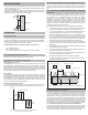
To start programming, press the key for 3 seconds to access the
Fahrenheit/Celsius mode. The lower LCD display will show the current status,
either for degrees Fahrenheit or for degrees Celsius. This annunciator will be
flashing. Then press either or key to toggle between the or scales.
Press key again to access the setpoint mode. The lower LCD will display the
current setpoint (flashing) and the upper LCD will display annunciator. Then
press either the key to increase or the key to decrease the set point to
the desired setting.
** Please note that this value as well as all the temperature related value are
in degree Fahrenheit as set in step 1.
Press key again to access the heating or cooling mode. The upper LCD will
display the current mode, with flashing annunciator, either for heating or
for cooling. Then press either the key or the to toggle between the
or operation.
Press key again to access the PWM differential mode. The lower LCD will
display the current PWM differential (blinking) and the upper LCD will display
annunciator. Then press either the key to increase or the key to
decrease the differential to the desired setting.
Press key again to access the PWM Cycle Length. The lower LCD will
display the current PWM Cycle Length(blinking), in seconds and the upper LCD
will display . Then press either the key to increase or the key to
decrease the delay to the desired setting. The increment is in 10 seconds. Press
key again to go back to normal operating mode.
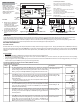
Description
Fahrenheit or Celsius Scale
Setpoint Temperature
Cooling or Heating
PWM Differential
Temperature
PWM Cycle Length
The default value is
Default setting is:
Default setting is:
Default setting is:
Default is:
F
75F
H1
8F
300 seconds.
LCD Display
75f
Si
P8f
8f
Hi
Programming Steps for PWM Control Mode
Note: Set PWM slide switch to ON
300
C8c
Keypad Lock:
Keypad can be locked to prevent tempering by unauthorized personnel. This
is done by pressing , and keys at the same time for three
seconds. The word “ ” appears on the LCD screen for 3 seconds which
indicates that the keypad is locked. Then input from the keypad is disabled.
Press , and keys at the same time again for another three
seconds to unlock the keypad. The word “ ” appears on the screen for 3
seconds which indicates that the keypad is enabled.
Factory setting: unlock
SET Up Down
SET Up Down
LC
Lf
o
o
Review Mode:Setting
Press both and keys at the same time to review the current control
settings. Then Press (or ) key to scroll through the settings in the
same order as Program Mode (F/C scale, Setpoint, Differential,
Heating/Cooling, Anti Cycle Time Delay etc.). To exit to normal mode,, press
one more time (eg. AC1) or press both
and at the same time. In this mode, the settings cannot be
changed.
Up Down
Up
Upfrom the last setting
Down
Down
Down
key
keys
Reset:
Press key if the following changes are made after the control is
powered up:
Slide switch settings
T
RESET
!
!
ime related parameters such as anti-cycle time delay or PWM cycle
length
After reset, the control will start from the beginning and run on these new
settings
max
Min
T1
95f
52f
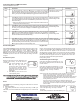
Troubleshooting Error Messages
If the upper LCD display shows flashing “Err” and
the lower LCD display shows S1, the sensor probe
is short circuited.
If the upper LCD display shows flashing “LLL” and
the lower LCD display shows S1, the sensor probe
is open circuited or the sensor temperature is out
of the lower range. The relay 1 will be de-
energized.
Si
E88
Si
Lll
Si
Hhh
If the upper LCD display shows flashing “HHH” and the
lower LCD display shows S1, the sensor temperature
is out of the upper range. The relay 1 will be de-
energized.
Use the same procedures as above with flashing “LLL”
Action: Verify if the sensor temperature is open circuited or out of the lower
range. If not, check for proper sensor operation by comparing it to a
known ambient temperature. The easiest way is to get an Azel
Technologies DS-60P digital temperature gauge which displays two P-01
sensor temperature. Connect this sensor to DS-60P and compare the
reading with the good sensor.
The second way is to obtain the P-01 resistance table from the
manufacturer. Then use a ohmmeter to measure the resistance across
the two sensor leads and compare to the temperature reading at the
sensor location.
Max/Min Memory Mode:
SET
Maximum and Minimum sensor temperature are
recorded in the memory. To view the max./min.
Temperature:
1. From normal operating mode, press
key once (eg. Just for 1
second).The upper LCD will display
the maximum recorded sensor
temperature and the lower LCD will
display the minimum recorded sensor
temperature.
2. Press once more to exit to
normal operating mode.
SET key