
User Manual

SETTING THE CONTROLS
QuickSet Feature:
Program Mode:
Quickset allows the user to change the setpoint temperature instantly without entering the program mode. Simply press (increase) or (decrease) key
during the normal operating mode. When the key is pressed, the setpoint is flashing to indicate that the setpoint value can be changed. Press the
button again to adjust the setpoint (press and hold for auto repeat function). Press key when finish or just walk away and it will return to normal mode after 30
seconds.
UP Down
Up/Down UP/Down
SET
General Note:
!
!
!
Press and hold the Key or Key to change the value continuously (auto repeat function).
To return to normal operating mode from the program mode, press and hold the key for 3 seconds. However, the system also return to normal operating
mode if no key is pressed for 30 seconds.
During the program mode, each time key is pressed, the data will be saved into the EEPROM and advance to the next setting(parameter). If no change of
value is required, just press key once to go to the next step (parameter).
Up Down
SET
SET
SET
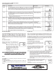
Steps
Step1
Step 2
Step 3
Step 4
Step 5
Procedures
SET
FC
Up Down F C
SET
S1
Up Down
SET
dF1
Up Down
SET
H1 C1
Up Down
C1 H1
SET
AC1 Up Down
SET
To start programming, press the key for 3 seconds to access the
Fahrenheit/Celsius mode. The lower LCD display will show the current status,
either for degrees Fahrenheit or for degrees Celsius. This annunciator will be
flashing. Then press either or key to toggle between the or scales.
Press key again to access the setpoint mode. The lower LCD will display the
current setpoint (flashing) and the upper LCD will display annunciator. Then
press either the key to increase or the key to decrease the setpoint to
the desired setting.
** Please note that this value as well as all the temperature related value are
in degree Fahrenheit as set in step 1.
Press key again to access the differential mode. The lower LCD will display
the current differential (blinking) and the upper LCD will display annunciator.
Then press either the key to increase or the key to decrease the
differential to the desired setting.
Press key again to access the heating or cooling mode. The upper LCD will
display the current mode, with flashing annunciator, either for heating or
for cooling. Then press either the key or the key to toggle between the
or operation.
Press key again to access the Anti-Short Cycle time delay. The lower LCD
will display the current time delay(blinking), in minute and the upper LCD will
display . Then press either the key to increase or the key to
decrease the delay to the desired setting. The increment is in 1 minute. Press
key again to go back to normal operating mode.
Description
Fahrenheit or Celsius Scale
Setpoint Temperature
Differential Temperature
Cooling or Heating
Anti-Short Cycle time delay
The default value is
Default setting is:
Default setting is:
Default setting is:
Default is: minutes
F
75F
1F
H1
0
LCD Display
0
75f
Si
8f i
If
Hi
Ac i
S1 S1
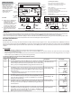
PWM
ON
OFF
240V COM 120V
RELAY 1
NCCNO
SENSOR INPUTS
AC INPUT
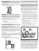
93
Down (Arrow)
Button
Up (Arrow)
Button
Reset Button
Backlit Switch
Setpoint
Temperature
Sensor
Temperature
Fuse
Relay Output
Status
Indicator LED
SET Button
PWM Switch
120 VAC
(HOT)
(COM)
LOAD
SENSOR
PROBE
(P-01)
Figure 5: Typical Wiring Diagram for DST-777D
with 120Vac Loads
WIRING THE CONTROL
Refer to Figure 4 for
typical wiring connections
for DST-777S and Figure
5 for DST-777D . Do not
use wire larger than 12
AWG as jumper between
terminal blocks (eg.
“120V” and “C”)
Programming Steps for Normal Control Mode (ON/OFF Control)
Note: Set PWM slide switch to OFF
POWER ON
All the slide switches (Backlit and PWM) should be set before the control is powered up (so the desired switch settings are scanned by the microprocessor).
However if the settings on the slide switches are changed after power is supplied, press the key so that the switch settings can be updated.
When the control is powered up, the model ID is displayed. Then the control will run Anti-short cycle delay(if any) and goes into normal operating mode in which
the Upper LCD will display the current sensor temperature and the Lower LCD will display the setpoint temperature.
RESET
Figure 4: Typical Wiring Diagram for DST-777S
with 120Vac Load
Terminal Representations:
240V is the hot of the 240Vac line voltage
COM is the neutral or ground of the line voltage
120V is the hot of the 120Vac line voltage
RELAY 1/RELAY 2
NC is Normally Close of SPDT switch and opens
when the relay is energized
C is Common of the SPDT switch
NO is Normally Open of the SPDT switch and closes
when the relay is energized
SENSOR INPUT
S1 S1 are the input terminals for sensor probe P-01
S1 S1
PWM
ON
OFF
240V COM 120V
RELAY 1
NCCNO
SENSOR INPUTS
AC INPUT
120 VAC
(HOT)
(COM)
LOAD
SENSOR
PROBE
(P-01)
RELAY 2
NC C NO
LOAD
Checkout
! Before power is applied to the
control, make sure that the
installation and wiring
connections are done correctly.
Also, ensure that the wires
connecting to COM and 120V
are not touching each other.
! Ensure that wires of the senor
probe are not touching each
other