
User guide
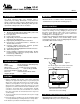

JUMPER PLACEMENT
TERMINAL DESCRIPTION
Factory installed jumper between L(JUMPER) and 3(JUMPER)
allows power to be switched on terminal 4NC and 4NO
Line Voltage Terminals(from left to right)
N 120 VAC Neutral Terminal Output to Circulator
N 120 VAC Neutral Terminal Input
L 120 VAC Hot Terminal Input
L/JUMPER See JUMPER PLACEMENT section
3/JUMPER See JUMPER PLACEMENT section
4/NC Normally Closed Terminal
3/C Common Terminal for 4/NC & 4/NO(connected to
3/JUMPER)
4/NO Normally Open Terminal (120 VAC Hot Output to
Circulator with jumper installed)
Note: Both N terminals are interconnected
Both L terminals are interconnected
Low Voltage Terminals
6/NO Normally Open Terminal
5/C Common Terminal for 6/NO & 6/NC
6/NC Normally Closed Terminal
R/24VAC 24VAC Hot Terminal Output
C/24VAC 24VAC Common Terminal Output
R/T 24VAC Thermostat Hot Terminal
R/W Thermostat Switching Terminal
Note: 24VAC outputs(R & C Terminals) can be used to power
electronic thermostat(eg. Azel Technologies D-135E)
OPERATION
When the thermostats(or any other low voltage controller
having SPST switching action) calls for heat, the relay is
energized to turn on both circulator(or line voltage load)
and boiler controller.
Thermostat calling for heat (R/T and W/T circuit is
made):
! Terminals 3/C & 4/NO are closed to turn on the
circulator(jumper must be installed between L/JUMPER
and 3/JUMPER)
! Terminals 3/C & 4/NC are open
! Terminals 5/C & 6/NO are closed to turn on the
boiler/burner control
! Terminals 5/C & 6/NC are open
Thermostat not calling for heat (R/T and W/T circuit is
not made):
! Terminals 3/C & 4/NO are open(circulator is turned off)
! Terminals 3/C & 4/NC are closed
! Terminals 5/C & 6/NO are open(boiler/burner control is
turned off)
! Terminals 5/C & 6/NC are closed
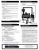
120 VAC
(HOT)
(COM)
OUT IN
24
Vac
Circulator
FUSE
3 4 3
Med. Temp
N N L L
120 VAC
NC
C
NO
C
4 6 5 6
R C R W
T T
24 VAC
JUMPER
NO NC
120 Vac
24 Vac
Factory
Installed
Jumper
N
L
Thermostat
(eg. Azel Tech, D-135E)
Power to
thermostat
Boiler/
Burner
Control
T
T
Relay
Coil
TYPICAL WIRING DIAGRAM
TROUBLE SHOOTING
When 120VAC is supplied to SP-81, the green indicator
light should be on. When the thermostat calls for heat, both
the red indicator light and the circulator should be on.
! If the green light is on and the circulator cannot be
turned on by the thermostat(red light is off), remove
the thermostat and put a piece of wire across the
thermostat terminals (R/T and W/T) to simulate
thermostat calling for heat. If the circulator can be turned
on along with the red light, then check the thermostat for
functionality.
! If both green light and red light are on and the
circulator cannot be turned on, re-tighten the screws
for the jumper on terminal L and 3 and try again.
! If red light is on all the time, check the thermostat for
functionality. Remove the thermostat from the SP-81
and put a piece of wire across R/T and W/T terminal to
simulate the thermostat calling for heat. If everything
works properly, then the thermostat is faulty.
! If the green light is off, check the fuse and the
presence of 120VAC power supply . If the fuse is fine
and there is no power output on R C (24VAC) terminals,
the transformer (model: 0511F) needs to be replaced.
P.O. Box 53138
10 Royal Orchard Blvd.
Thornhill, Ontario, Canada L3T 7R9
Ph: 905-223-5567 Fax: 905-223-3778
Email: info@azeltec.com
www.azeltec.com
AZEL
TECHNOLOGIES INC.
Please visit our website for other products
Note: Press down the white
lever to insert wire into the
screwless terminal blocks
NC: Normally Closed
NO: Normally Open
C: Common
2 32 34 5