
Install Instructions
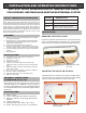

OPERATION OF THE BUTTONS ON THE
FRONT COVER:
MAX-MIN
From the normal temperature display mode(no wording
such as MAX or MIN on the LCD), press MAX-MIN button
once to display the recorded maximum temperature of
OUT(supply) and IN(return) piping. MAX appears in the
temperature LCD’s.
Press MAX-MIN button again to toggle to the recorded
minimum temperature of OUT(supply) and IN(return)
piping. MIN appears in the temperature LCD’s.
Press MAX-MIN button again to return to the normal
temperature display mode.
RESET
8Press RESET button to reset both the maximum and
minimum temperatures in the memory.
C/ F
8Press the C/ F button to toggle between C and F.
° °
° ° ° °
INSTALLATION:
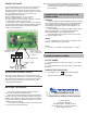
WIRING THE DS-60P
First of all, decide if the wire is going to run through the
bottom or back opening. In case of running the wire
through the bottom opening, remove the plastic plug by
sliding outward. For hydronic heating system, run a pair of
wire (18-20AWG) from each of P-03 sensor to the
corresponding terminal blocks:
Sensor of Supply Piping to “T1 T1” or “OUT”.
Sensor of Return Piping to “T2 T2” or “IN”.
For other systems, T1 corresponds to location 1 and T2
corresponds to location 2 of the sensors.
When 24VAC input is applied, the power consumption
from the lithium battery will be disabled. Always pull away
the plastic tab from the battery to activate the battery
power or as backup power.
INSTALLING THE FRONT COVER
This is the reverse process of removing the front cover.
The hinges on the bottom of the front cover can be aligned
with the base to provide pivot for the front cover to close.
Swing the top part of the front cover all the way until it
snaps tightly with the base.
OTHER OPERATION ISSUES:
OUT OF RANGE
8If the temperature is under -58 F (-50 C), “LLL” will be
displayed
8If the temperature is over 302 F (150 C), “HHH” will be
displayed
LOW BATTERY INDICATOR
8If the battery is low, symbol will be flashing.
Change the battery as soon as possible.
° °
° °
MOUNTING THE SENSOR:
The sensor P-03 is designed to strap on a pipe or
insert onto a temperature immersion well.
Sensors should be strapped to the pipe with cable tie.
The flat side of the sensor should be resting on the pipe. In
addition, they should be covered with a layer of insulation
to minimize the effects of ambient temperature for a more
reliable temperature reading.
The sensor P-03 can also be insert onto a 3/8”(10mm)
or ½”(12.7mm) ID temperature well.
P.O. Box 53138
10 Royal Orchard Blvd.
Thornhill, Ontario, Canada L3T 7R9
Ph: 905-223-5567 Fax: 905-223-3778
Email: info@azeltec.com
www.azeltec.com
AZEL
TECHNOLOGIES INC.
Note: Do not run sensor wires parallel to other electrical wiring
or telephone wires. In case there is strong source of
electromagnetic interference, twisted pair 20AWG wire is
recommended.
Please visit our website for other products
IN
OUT
T1 T1
T2 T2
24VAC
Printed Circuit Board
behind the cover
24VAC
SUPPLY
PIPING
RETURN
PIPING
P-03 Sensor Probes
Switch for setting
default display unit
in ° °C or F after reset
or power up.
Plastic plug removed