
User Guide

Description
D-28F digital thermostat is specifically designed for Radiant Floor Heating
Systems. It is so flexible that it can be used to control either ambient(air)
temperature (A Mode) or floor temperature (F Mode) or a combination of
air temperature with floor temperature limit(AF Mode). An auxiliary remote
sensor is provided to measure slab temperature in order to control the floor
temperature within desired maximum and minimum limits.
Installation
1. Look for a location which has a constant temperature in the house and
it is no near the door entry of heater or air conditioning outlet. The
mounting height should be about five feet above the floor.
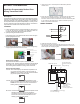
2. Open top housing as illustrations below :
Press down the lever on the left hand side of the enclosure and open
the unit by lifting the front cover.
3. Before installing the thermostat on the wall, it must be configured by
using the jumpers at the back for the front cover.
INSTRUCTION MANUAL
Digital Non-Programmable Radiant Floor
Heating Thermostat D-28F
Easy
V
iew Large
Display
Heating
Cooling
Heat/Cool Mode Jumper
(2nd jumper from top)
Back of front cover
Heating/Cooling Mode:
Use the Heat/Cool Mode Jumper to select the system
operating mode. Heating should be selected for A/F/AF Mode
and Cooling can only be selected for A mode. Functions of
floor heating will be disabled if cooling mode is selected.
General Operating Mode:
A mode: controls and displays the ambient temperature. Do
not connect the floor sensor. Insert the jumper to
enable the room sensor and LCD will show ambient
(air) mode symbol as shown below:
F mode: controls and displays the floor temperature. Floor
sensor should be connected. Remove the jumper to
disable the room sensor and LCD will show Floor
Heating mode symbol as shown below:
AF mode: controls and displays the ambient temperature with
maximum floor limit. Floor sensor should be
connected. Insert the jumper to enable the room
sensor and LCD will show Ambient/Floor Limit
Heating symbol as shown below:
Enabled (jumper inserted)
Disabled (jumper removed)
Room Sensor Jumper
6
LOAD
Floor Sensor
5
4
2
1
4
COM
NC
NO
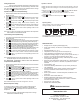
WIRING DIAGRAM:
5. Follow the wiring diagram on Figure 1. Insert the wires into the terminal
blocks and use a screwdriver to tighten the screws on top of the
terminals. Use the screw to fix the terminal cover back to the back plate.
If your system is other than this type, please consult with your local
dealer or a professional electrician.
4. Remove the screw on the back plate and take off the protective
terminal cover.
6. Install the back plate on the wall.
7. Put the front cover back to the back plate by aligning two hooks on the
right hand side of the inner enclosure. Make sure there is a click sound
when two parts are snapping together.
FIGURE 1
8. Press RESET before starting the operation of the thermostat.
1.Standby button
when thermostat
in operation
2. Selection button
for setting adjustment
Increase/Decrease
temperature setpoint
or
change settings
ECONOMY setpoint
COMFORT setpoint
Press “RESET” before changing
the internal settings.