
Data Sheet


55
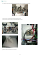
13. Tests 1 and Arduino program installation
Electrical functioning tests
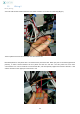
Before electrical functioning testing and in order to avoid all problems, wiring verification is important. It is appropriate
to recheck the Wiring I and Wiring II steps. Here are the connections from the terminal blocks:
Terminal
block
Connected to
Function
W1
(+12V) Battery, charger red plug (CHR), thin yellow wire, RB_24
permanent +12V
W2
Battery (GND), W3 (a long wire must link the two terminal blocks in order
to get only one ground), Power Module (PM10), Thick brown wire from the
mast, thin black wire Servo controller (CS_-) , Button relay (RB_A2)
Ground
W3
W2, obstacles sensors blue wires, outlet for charge (CHR-black wire), black
thin wires from USB cables linked to PB, black wire linked to MS1, GND
from ASM1
Ground
W4
RB_21, VD from ASM1, Sick sensors brown wires
Temporary +12V
W5
RB_11, CS_+ (red wire ), MS2
+5V temporary
W6
Thin red wire from the mast , RB_A1
( +12V) relay Command
W7
Thin green wire from the mast , CS_11
Servomotor data
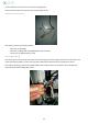
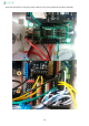
Check the position of the different switches on boards: PM: 5V , ON / MS: PWR Now here is the list of tests to be
done to verify the good electrical functioning of the robot:
Button is OFF position, charger being unconnected.
- Everything must be switched off
Switch the button in ON position, charger being unconnected
- Button lit, micro USB from the mast supplied with 5V (connect a tablet to verify it)
- ASSER1, ASSER2, Mega ADK, CS and shield Bluetooth lit
Button in ON position, charger connected:
- Everything is lit (i.e. previous parts + power module+ Arduino mini-relay Check that the Power Bank is
blinking (it means, it is charging)
Button in OFF position, charger connected
- Only Power Module and Arduino mini relay are lit
- Power Bank is charging (it blinks) and battery is charging ( charger LED is lit in red or green