
Data Sheet

47
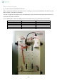
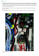
Charger [CHR] Electrical wiring
At the same time you connect the Power Module PM9 to the CHR plug, you can connect CHR to the ground on the W3
terminal block and the second red wire of the CHR connector to the permanent +12V (W1 terminal block). Detailed
explanation: the permanent +12V and PM_9 are not linked because, if it was the case, the 4000mAh battery would
supply the power module which transforms the 12V in 5V. This specific board is supplying the power bank (through
the connection between PM_3 and RA_2). Their Grounds being common, it would drive to discharge one battery (4Ah
one) to supply another one (10Ah). So, robot autonomy would be reduced.
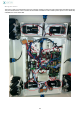
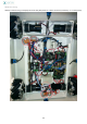
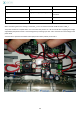
Logic wiring
At this point, it is possible to connect the motor feedback sensors which indicate motors speed and allow the Mega
ADK to control them (closed loop command) .The Mega ADK can also be connected to the servo boards.
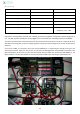
The motor sensors have 4 wires. Be careful, they don’t use always the same code. To identify them, you have to look
at their starting point when considering the electronic board at the motor level. The most outside corresponds to the
B (4) signal and the most inside one to the +.
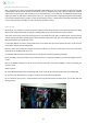
For example, PIN 19: (4 motor 2) corresponds to the most outside wire (so sensor B) from the motor 2; He has to be
connected to the PIN 19 of the Mega ADK.
PIN 22: (3 motor 3) corresponds to the third wire (from inside out), so A sensor of the motor. He has to be connected
to the PIN 22 of the Mega ADK. And so on.
For the Mega ADK connectors towards the servo cards, please consider the following examples:
PIN 2: (E1 ASM1): starting from PIN 2 to go to the E1 of board 1. The board 1 (ASM1) is the one controlling the motors
1 and 2.
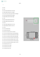
PIN 11: (E2 ASM2): starting from PIN 11 to go to the E2 of board 2. The board 2 (ASM2) is the one controlling the
motors 3 and 4.
Other examples:
Pin 14: TX Bluetooth board must link the Mega ADK to the small Bluetooth shield located also on the Mega ADK
Pin 16: Serial 2 for Arduino Servo controller : to link to CS (see the picture in Wiring II)
Pin 24 : Proximity sensor Front : must be linked to the thin black wire from the front sensor (to be done with the
Wiring II phase)