
Data Sheet

43
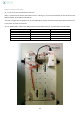
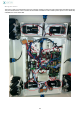
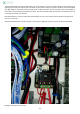
Boards wiring
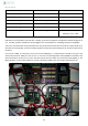
Connector
linked with
Function
MS_1
W3
Ground
MS_2
W5
Temporary +5V
MS_3
ASM2_3
Temporary +12V
ASM1_4
W4
Temporary +12V
ASM1_5
W3
Ground
ASM1_6
ASM2_6
(red and black wires)
Temporary +12V + GND
Explanation: The mega ADK is powered with +12V (MS_3) (an internal regulator managed the required voltage) for its
use. +5V (MS_2) powers the different parts plugged in the red and black pins of the Mega expansion shield (MS).
The motor controller boards are powered with 12V. The jumper VD=VS should be set. It links the 2 inputs VD & VS. As
described on the mega ADK, an internal voltage regulator manage the internal voltage for the numical components of
the board.
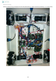
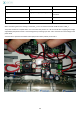
So we use the ASM1_4 as temporary +12V input and the ASM1&2_6 is recuperating this voltage to bring it to the
other board terminals. ASM2_3 is used, in turn, as +12V source for the Mega ADK. Ground (GND) is connected to the
W3 terminal block. So there are on one or the other board, two wires which are connected to GND (ASM1_5) The
Mega shield has a small switch 5V/PWR. It must be positioned on PWR to pass the voltage supplied by the PB.