
Data Sheet

32
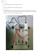
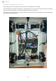
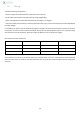
Wiring Relay Button
You will need to cut and strip the red and black wire (0.25mm²) to be used for control.
4 red 1,5mm² wires go on port 11, 14, 21 and 24. Pass through the central hole every wire except 2 large red from
RB_14 RB_21, which must pass through the other hole (see photo).
The more detailed explanation of the connections is given in Wiring I. For now, just check that the wires go through
the right holes and that the little red is A1 and A2 on the little black.
Wire
From
Through
To
Function
Thin black
A2
Central hole
W2
Ground
Thin red
A1
Central hole
W6
Command + of RB
Thick red
11
Central hole
W5
+5V temporary
Thick red
14
Front hole
RA_COM
+5V permanent
Thick red
21
Front hole
W4
+12V temporary
Thick red
24
Central hole
W1
+12V permanent
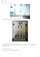
P2 & P4
Add P2 and P4 parts with M5*12 BHC screws
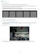
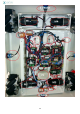
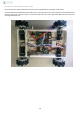
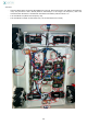
9. Chassis assembly (lower face)
In this phase 16, pictures are taken from an already assembled base. You must not take in account the wiring of the
already mounted parts.
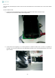
Adding battery
Place the battery as shown on the picture and fix the brackets with the bolts supplied with the nylon spacers.