Assembly and operating instructions for Ubbo Maker 2 1
Index Introduction : .................................................................................................................................................................... 3 1. Part list ...................................................................................................................................................................... 4 2. Tooling.................................................................................................................................
Introduction : This guide shows how to setup and to self-assembly the robot as a kit. It provides also explanations on its physical functioning. The CD provided with the robot includes the source code as well as some explanation on how the software works. Some parts are pre-soldered, pre-drilled and other preparation operations to allow the assembly the robot with the minimum of tools.
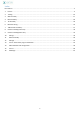
Part list Item Qty Picture Screws and hardware Screw BHC M5*12 60 Hexagonal screw M6*20 11 Screw BHC M3*12 4 Nylon spacer 10mm 30 Electrical terminal box 4*5 4*3 6*2 Hose clamps 10 4
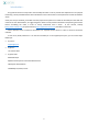
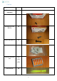
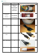
Article Qty Electrical wires 2 bags of 10 (5 colors) female/female Image 1 bag of 10 male/female Electrical wires, 1,5mm² 0,25mm² 3m (red black) 1m (red black) Scratch tape 20 cm USB A/ Micro USB cable 2 USB A / Mini USB cable 1 USB A / USB B cable 1 Battery connector 1 5
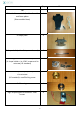
Item Qty Tilt Tablet holder + anti-theft cable + 2 small oval foam plates 1 (Disassembled item) U shape piece 1 D shape shaft ( with a flat spot at the end) 1 Connecting element with the D shape shaft / U shape holder + its 4 CHC screws and its setscrew (US standard) 1 Servomotor coupler output /D shape shaft + its setscrew 1 (US standard)+ small locking screw Ball bearings 1 High torque digital servomotor+ small screws 1 6 Picture
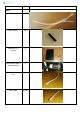
Item Qty Picture Mast Rods 2 Black spacer 20 Black box + 4 screws 1 Push button with 4 soldered wires 1 5V power supply line 1,5m Data cable 1,5m 7
Item Qty Picture Shell Pre-drilled shell 1 1 USB B Extension cable+ 2 flat Philips-head screw M3*12 Obstacles sensors + nut and ferrule 4 8
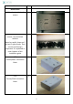
Item Qty Picture Mobile base White chassis with its 4 motors 1 Mecanum wheels + 4 sets of screws, nuts and black washers 4 Note: be careful, there are 2 left and 2 right wheels. Their correct positioning is important.
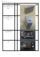
Article Qty (P3) 2 Image Carcass/mast connection block (P4) 2 Carcass/Shell connection block Arduino Mega ADK or compatible[MAD] 1 Mega Sensor shield V2.
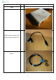
Item Qty DF-Bluetooth v3 Shield [BT] 1 Picture 2 Motor servo board (ASM) Power Module [PM] 1 5V Relay module for Arduino [RA] 1 Control board for Servo [CS] 1 11
Item Qty 12V Relay for the Button [RB] 1 Power bank [PB] 1 4000mAh NiMH battery 1 Battery holder (angle bracket) 2 Module / Power Module connection cable Relay 1 Small black plastic washer 1 M5 nuts 3 Picture 12
Item Qty Picture Accessories 12V Battery charger 1 1 CD with : Arduino source code Android source code Ruby source code Apk libraries 13
2.
Cutter Protective gloves 1 1 pair Protective glasses 1 pair OPTION : thread lock 1 1 OPTION : Hot glue gun with glue sticks 15
Prerequisites: use of terminal blocks The gray and orange terminals are used to pool all cables that are inserted there. To insert the cable, first make sure that it is bare. Open a clip, insert the wire and close it. The clips can be quite difficult to open.
3. Shell assembly Obstacle sensors installation Tighten nut at sensor Mount the washer on the shell, clip the sensor, and then tighten the nut To get an obstacle detection distance of around 20cm, the adjustment screw must be in the shown position.
4. Mast assembly Mast assembly Mount the spacers on a rod as shown on the picture, and then mount the second rod.
Black box assembly Insert and screw the push button in the black box, then screw on the black box on the mast as shown on the picture below Adding cables on the mast Slide the cables in the black box leaving a small overhang of 10 cm (be careful not having a too long overhang driving to reduce the length at the bottom) 19
With the neoprene glue, glue the wires down to the bottom of the mast on the edge Tip: use a hose clamp to tighten the cables at the bottom of the mast to avoid they have too much freedom 5.
Spacers Screw the Nylon spacers as follows: Use the BHC M3*12 screws instead of the small screws supplied in the spacers bag. Mount the connecting piece on the U shape piece. Be careful with the mounting direction of the fastening screw downwards! Be careful with the connecting piece side (on the right hand side) ! Mount the piece securely tightened with 2 screws The Axyn logo being asymmetric, it can be used as a mark.
Adding the coupler on the servomotor Turn the motor clockwise until stop is reached To mount the coupler, use the following procedure: hole down, shifted one step to the left 22
Screw the screw inside the coupler Screw the shaft on the coupler Tip: putting some thread lock or nail polish will avoid a loosening of the small black screw ! Be careful, do not over tighten the small black screw, you could damage the bolt thread 23
U Shape Positioning of the U shape piece, insert the whole with the servomotor Tighten the connecting piece fastening screw from the bottom and screw the 4 nuts on the nylon spacers 24
6.
Here is the way to use the different wires (be careful the servomotor and the base are note using the same color code.
7.
Tablet holder mounting Add the gear and the 2 mobile piece parts, then screw the upper plate (at the top only) Slide the lower mobile piece part by spreading slightly the 2 plates then screw the lower part 28
You can add foam trays depending on the tablet. At last, the lower mobile part can be blocked with the padlock. The padlock is given with its cable. So it allows you reusing it for other purpose (laptop PC, notebook for example). If you wish using it only for the robot, you can see it at the level of the part which holds the cable.
8.
Fix the Power Bank Fix the Power Bank (PB) with some scratch (hook and loop) tape. Relay Fix the Power Bank (PB) with some scratch (hook and loop) tape. Power Bank wiring Cut an USB/Micro USB cable in order to get 2 wires and then strip them. White and green wires are not useful here. The micro USB is used to recharge the PB (PB_mUSB). USB port is used to 5V supply the robot (PB_USB2A) Tip: Make a mark with tape in order to distinguish the 2 cables.
Wiring Relay Button You will need to cut and strip the red and black wire (0.25mm²) to be used for control. 4 red 1,5mm² wires go on port 11, 14, 21 and 24. Pass through the central hole every wire except 2 large red from RB_14 RB_21, which must pass through the other hole (see photo). The more detailed explanation of the connections is given in Wiring I. For now, just check that the wires go through the right holes and that the little red is A1 and A2 on the little black.
Adding spacers on the chassis The spacers must be positioned as indicated on the picture: Assembling the electronic boards with the chassis In this step, do not take in account the visible wiring on the picture.
Add the anti-vibration washer On the mobile part of the chassis, put out the metal washer and replace it by the black plastic one and screw. Tips: Use if possible thread lock on the screw. This plastic washer improves the behavior of the chassis against vibration on the front part.
Installation of the wheels on the chassis Use the long screws, the black plastic washers and the 2 nuts provided in the small bag. ! Be careful with the orientation of the wheels. They should be set as it is shown on the picture below. (From the back side view, the rolls should draw an arrow pointing toward the front of the chassis). Tips: Before mounting the wheels, put out the small black screws on the motor shaft adaptor and rescrew them with thread lock (to resist to vibration).
Wheel tests Turn manually each wheel (Be careful to avoid contact risk between the red and black wire of each motor before testing). 2 issues could be found: 1- A ‘click’ can be heard (the flanges of the encoder on the back of the motor touch the sensor. Identify the concerned ones and put them straight back. 2- If the motor turns irregularly, i.e. in certain position it’s harder to make it turn, it’s due to a problem of coaxiality.
Installation of the USB B extension cable Insert the extension cable in the hole on the back of the mega ADK board and plug it on the board. The small Arduino board dedicated to the tablet servo control (not seen in the picture below) can cause difficulties for insertion. In this case, you can unscrew it to allow the operation and screw it again when USB connector insertion in the mega ADK board is ok.
10. Wiring I The electrical wiring is designed to: - allow re-charge of the robot batteries (12V & 5V) at the same time. - let the robot works without interruption during charger plug/unplug - power automatically the whole robot with batteries or charger if it’s plugged - control the power with one button on the top of the robot with only a small current requirement and independently from the charging For assembly, you have to use the terminal block (grey & orange).
You need : - - 4 terminal block with 5 connections (W2 & W3 for the ground,, W1 for permanent +12V, W4 for the temporary +12V). The permanent +12V is directly linked to the battery or to its charger. The temporary +12V is not connected when the button is switched off and linked to the battery with the switch is on.
Electric wiring of the relay A1, 11, 14, 21, 24 ports are indicated on the relay Relay is activated by the button (that will be wired in « Wiring II »). A 12V tension between A1 and A2 will connect (RB_14 with RB_11) and (RB_24 with RB_21). The relay is a type DTDT monostable. The 11/14 couple will be used for 5V and the 21/24 couple will be used for 12V. In this phase, A1 is left unconnected. Tip: You should make a mark on the different wires to know where each one is connected to from the inside.
Wiring the motors The motors 1 and 4 are positioned on the front, with the number 4 at the same side as the plug and the Arduino board. They are linked with the motor controller boards ASM1 and ASM2 as follow: ASM1 powers up the motors M1 & M2, and ASM2 the motors M3 & M4.
Boards wiring Connector linked with Function MS_1 W3 Ground MS_2 W5 Temporary +5V MS_3 ASM2_3 Temporary +12V ASM1_4 W4 Temporary +12V ASM1_5 W3 Ground ASM1_6 ASM2_6 (red and black wires) Temporary +12V + GND Explanation: The mega ADK is powered with +12V (MS_3) (an internal regulator managed the required voltage) for its use. +5V (MS_2) powers the different parts plugged in the red and black pins of the Mega expansion shield (MS). The motor controller boards are powered with 12V.
Batteries wiring Battery is linked to the ground (W2) and to the 12V (W1) thanks to a white connector (marked by « C » on the picture) 44
The Power Bank (PG) is having two USB cables. The micro USB one is used to recharge the PB, the normal USB one is supplying the 5V (connect it to 2A). The two cables are connected to the same “ground”. However, the micro USB red wire (PB mUSB) is connected to NO (normally open) of RA2 mini-relay. The normal USB red wire (PB_USB2A) is connected to NC (normally closed) of RA1 mini-relay. The mini-relay RA3, COM, corresponds to the permanent 5V. He is connected to the RB_14 connector.
Connector Linked with Function RA_2 PM_3 +5V when loader connected RA_B PM_7 (red and green), PM_8 (black) Commande du Relais Arduino relay command PM_9 CHR +12V when loader connected PM_10 W2 Ground When considering the 2 wires coming out from RA_2, one is connected to the PB mUSB the other to PM_3. The power module has a 5V/VR switch. You must select the position 5V . VR one would allow supplying the voltage adjustable by the potentiometer.
Charger [CHR] Electrical wiring At the same time you connect the Power Module PM9 to the CHR plug, you can connect CHR to the ground on the W3 terminal block and the second red wire of the CHR connector to the permanent +12V (W1 terminal block). Detailed explanation: the permanent +12V and PM_9 are not linked because, if it was the case, the 4000mAh battery would supply the power module which transforms the 12V in 5V.
Pinout ------- Pin 0: NC Pin 1: NC Pin 2: (E1 ASM 1) PWM wheel Front Right Pin 3: (M1 ASM 1) DIR wheel Front Right Pin 4: (3 motor 1) Encoder signal A wheel Front Right Pin 5: (E2 ASM 1) PWM wheel Back Right Pin 6: (M2 ASM 1) DIR wheel Back Right Pin 7: NC Pin 8: (E1 ASM 2) PWM wheel Back Left Pin 9: (M1 ASM 2) DIR wheel Back Left Pin 10: NC Pin 11: (E2 ASM 2) PWM wheel Front Left Pin 12: (M2 ASM 2) DIR wheel Front Left Pin 13: NC Pin 14: TX Carte Bluetooth Pin 15: RX Carte Bluetooth Pin 16: Serial 2 for A
Here is how is wired the charger plug. When this plug is connected, it links together all the 12V (the permanent 12V and the Power Module input). The charger can supply all the elements of the robot (battery 4Ah and Power Bank 10 Ah + mobile part and upper part of the mast if the switch is in ON position).
11.
First, slide the mast in the shell and then pull the cables of the mast through the central hole.
12. Wiring II Relay wiring You must take the thin red wire from the mast cable and link it to red wire from the relay (RB_A1) The thin yellow wire from the mast cable must be linked to W1. Detailed explanation: the yellow wire is connected to the permanent 12V. When you push on the button (pushed-in position), it makes contact between the thin yellow and the thin red wire. The thin yellow one turns from «unconnected » to +12V.
Connect the thick marron wire from the mast on W2 (ground) Connect the thick blue wire from the mast on W5 (temporary 5V) Obstacles sensors wiring Sick sensors must be connected as follows: - Blue ones on W3 (GND) Black ones on Mega ADK shield (MS) (please refer to Pinout) Brown ones on W4 (temporary +12V) Servo logical wiring Link the thin green wire from the mast cable to the female plug. This female plug will have to be connected to the Servo Controller (CS_PIN11).
Verify that logical PINs are well connected (in addition to the motors feedbacks from MS to ASM 1&2) 54
13. Tests 1 and Arduino program installation Electrical functioning tests Before electrical functioning testing and in order to avoid all problems, wiring verification is important. It is appropriate to recheck the Wiring I and Wiring II steps.
Arduino code upload If you are connected to internet, the driver managing the Arduino board should be installed automatically. Preferably use the Arduino 1.0.6 stable version. The « CHECK » button allows verifying that code compiling is correctly executed and is ready to be uploaded on to the board . The “Upload” button allows sending compiled code in to the board.
With this page, you can create an account or connect with an already existing account.
If you select the « Users management » button, you enter the menu allowing to grant access to a user enabling him to connect to the tablet from the web page NB : This email has to be created via the webpage To validate an account, you just have to give an email. To exit this page and step back to the previous menu press the « return » key. Configuration If you press the third button of the home page, you enter the configuration page.
Always on the « Configuration » page, if you click on the « manual mode » button, you go directly to the chassis test page. After having clicked on the « connection » button, the buttons turn from « grey » mode to « blue » one. Then you can test the robot movements. To exit this mode, you click on « stop the connection » and with the « return » key of the tablet and step back to the previous menu.
15. Tests II Those tests are to do preferably after charging the robot (1 night). Sensors tests Go to manual mode The robot has to stop when meeting an obstacle (except if this one is dusky) Moving tests Connect to the robot through internet (https://ubbo.cleverapps.io/users/sign_in) (Chrome recommended) Try all movements. Tilt test Still with internet navigator, move the tilt using slider. Connection stability test Disconnect / reconnect several times.
16. Web Page https://ubbo.cleverapps.io/ Main page for identification if you have already subscribed or the page to create your account These information have to be similar to the ones in the memory of the robot you want to connect with.
The screen is divided into 4 areas: - The upper right window displays the user’s webcam picture below, the dashboard : From the left to the right, we get: - o Mute or unmute microphone o Background image dimension selection: As the image quality is linked to the quality of the Wifi connection, it is possible to decrease the size of the remote video picture when its quality is bad and so avoiding pixilation.