INSTALLATION INSTRUCTIONS FOR PART ASWC ASWC Axxess Steering Wheel Control Interface Installation Manual KIT FEATURES • • • • • • • One Interface does it all - No additional interfaces needed Designed to be compatible with all major radio brands Auto detects vehicle type, radio connection, and presets controls Can be manually programmed for most vehicles Memory retains settings even after battery disconnection or interface removal Connection placements are all organized behind the radio USB updatable TOO
Table of Contents Preface .............................................................................................. 3 Overview – Introduction to the ASWC Interface and Wiring Harness .................4-5 ASWC – Section 1: Installation ....................................................................6-7 – Section 2: Programming ................................................................8-9 – Section 3: Troublshooting Auto Detect Mode .............................................................
Preface What you need to know before you begin 1) Know the correct year, make, and model of your vehicle. 2) Be sure that the radio you are installing is compatible with the Axxess steering wheel control (ASWC) interface (refer to the aftermarket radio owner’s manual). 3) Go to the Axxess website (www.axxessinterface.com) and click on “Steering Wheel Control” (SWC), which is located on the right side of the screen.
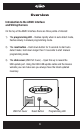
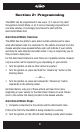
Overview Introduction to the ASWC Interface and Wiring Harness On the top of the ASWC interface there are three points of interest: 1) The programming LED – flashes rapidly when in auto detect mode, flashes slowly in manual programming mode. 2) The reset button – Hold down button for 3 seconds to start auto detect mode; hold down longer then 10 seconds to start manual programming mode. 3) The slide cover (USB Port Cover) – Open this up to reveal the USB update port.
Overview Below are the wire colors for the ASWC. Please visit the Axxess website at www.axxessinterface.com for detailed information on your specific vehicle and for what color wire(s) to use with the ASWC interface. Pin-1 Pin-2 Pin-3 Pin-4 Pin-5 Pin-6 Pin-7 Pin-8 Black/Green Pin-9 Red (tip of 3.5 mm connector) Pink White/Green Yellow/Green Green/Orange Gray/Red Black Blue/Pink Pin-10 White (ring of 3.
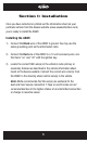
Section 1: Installation Once you have collected or printed out the information sheet on your particular vehicle from the Axxess website (www.axxessinterface.com) you’re ready to install the ASWC. Installing the ASWC 1) Connect the Black wire of the ASWC to ground. You may use the same grounding point as the aftermarket radio. 2) Connect the Red wire of the ASWC to a 12-volt accessory wire, one that turns “on” and “off” with the ignition key.
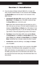
Section 1: Installation 4) If you are using an Eclipse, Kenwood, Metra OE, or a newer JVC radio, plug the included female 3.5 mm connector with the Brown and Brown/White wires into the male 3.5 mm connector of the ASWC harness. • For Kenwood and select JVC: Connect the SWC wire (normally Blue/Yellow) to the Brown wire of the ASWC. Isolate and tape the Brown/White wire, it will not be used. Note: Some newer Kenwood radios will auto detect as a JVC.
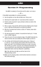
Section 2: Programming The ASWC can be programmed in two ways. (1) It can do it by itself through Auto Detect Mode, or (2) it can be manually programmed in non-data vehicles. It is strongly recommend to start with the Auto Detect Mode first. Auto Detect Mode: Overview The ASWC has the ability to auto detect certain vehicles and to know what aftermarket radio it is connected to. The vehicle info sheet from the Axxess website (www.axxessinterface.
Section 2: Programming the ASWC is looking for the vehicle and the radio. Go to step 4. --- Or --If the ASWC was installed in a vehicle previously: 2) Turn the ignition on, the LED will flash once, then go out. 3) Hold down the reset button for 3 seconds and then release it. 4) Perform action required for your particular vehicle as noted in the vehicle info sheet. 5) After a couple of seconds the LED should stop flashing and not light up for 2 seconds. At this point do not push any buttons.
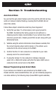
Section 3: Troubleshooting Auto Detect Mode So you tried the auto detect feature and at the end the LED did not stay solid red. Instead it started flashing, meaning that the ASWC did not detect the vehicle. Follow these steps to determine what may have happened: 1) Verify that you have 12-volt accessory and a good ground to the ASWC. Sometimes the factory ground is not sufficient, a chassis ground is highly recommended.
Section 3: Troubleshooting Note: Not every radio will have all the possible SWC commands on the steering wheel. Aftermarket radios that do not have Bluetooth will not recognize the PTT (Push To Talk) or “On/”off” Hook” commands; however those buttons can be manually programmed to do other commands in some cases. Please refer to the radio owner’s manual or wireless remote for specific commands that the radio will recognize. 1) Complete connections to the vehicle and to the aftermarket radio, make sure the 3.
Section 3: Troubleshooting 5) Now press and hold the “Volume Down” button until the LED goes solid red. Release the button and the LED will turn “off”. The “Volume Down” has now been programmed. 6) At this point go to the ASWC Legend Button Assignment (remapping/manual programming) section, page 19, and continue with “Seek Up/Next” button.
Section 3: Troubleshooting 11) Then the LED will flash, up to 11 times, depending on what radio the ASWC thinks it’s connected to. 12) Make sure the number of flashes match what radio you have installed. Refer to the Changing Radio Type section, pages 13-14. 13) If the LED flashes match the radio then hold down the “Volume Down” button until the LED goes solid red. 14) Programming for the vehicle and the radio is now complete. Test out the steering wheel control functions to make sure it works correctly.
Section 3: Troubleshooting 5) Here is the chart to show how many presses of the “Volume Up” button is needed for which radio you are trying to program: 1 2 3 4 5 6 7 8 9 10 11 Eclipse Kenwood Clarion “Type 1” Sony and Dual JVC Pioneer and Jensen Alpine* Visteon Valor Clarion “Type 2” METRA OE 6) Once the radio manufacturer has been selected hold “Volume Down” for at least 5 seconds.
Section 3: Troubleshooting 4) Press and release the “Volume Up” button for the desired radio number (please refer to the ASWC legend). For each press the red LED. It will go “on” and then “off” when released for feedback. 5) When the desired radio type has been reached, Press the “Volume Down” button. 6) The LED will go on and will remain on (approximately 3 seconds). The ASWC is internally computing and storing this new information. 7) The LED will go “off” indicating it is completed.
Section 4: Remapping Remapping the SWC (Steering Wheel Control) Buttons Once you have the ASWC programmed you can then change the steering wheel control button assignment(s). Such as, programing the “Seek Up” button as a “Mute” function. Follow the steps below to remap the SWC buttons: 1) Ideally have the ASWC visible, so you can see the LED flashes to confirm button recognition. 2) Turning “off” the radio is recommended.
Section 4: Remapping Resetting Orginal SWC Settings If for any reason after remapping the steering wheel controls you want to revert back to the original steering wheel control settings, follow these steps: 1) Within the first 20 seconds of turning the ignition on. Press and hold down the original “Volume Down” button (not the “Volume Down” button you just remapped) for at least 25 seconds. 2) The LED will turn on then release the “Volume Down” button and the LED will turn “off”.
ASWC Ledgend For A and B: Short flashes represent the steering wheel control wire(s) that are not connected to the vehicle from the ASWC. Long flashes represent wire(s) that are connected to the vehicle. A.
ASWC Ledgend *Note (section B): If the ASWC flashes 7 times and you do not have an Alpine radio connected to it that means that the ASWC did not see any radio connected. Verify the 3.5 mm connector is connected to the SWC input on the radio. C. Button Assignment (remapping/manual programming) 1. Volume Up 10. Band 2. Volume Down 11. Play/Enter 3. Seek Up/Next 12. PTT (Push To Talk) 4. Seek Down/Prev 13. On Hook 5. Source/Mode 14. Off Hook 6. Mute 15. Fan Up 7. Preset Up 16. Fan Down 8.
INSTALLATION INSTRUCTIONS FOR PART ASWC IMPORTANT WARNING This product includes instructions for installation which must be carefully followed. The instructions are worded in such a manner to assume that the installer is capable of completing these type of electronic installations.