
User's Manual
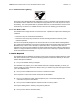
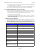
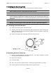
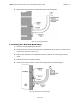
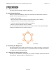
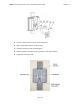
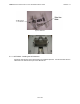
Table Of Contents
- 1 Preface
- 2 AB-MAX Product Overview
- 3 Pre-Installation
- 4 Installing the Mounting Poles
- 5 Radio Installation
- 6 Installing the Interconnect Cables
- 7 Grounding the System
- 8 Installing the NIA/Power Adapter Hookup
- 9.0 Configuring the ABMAX Access Point Base Station
- Appendix A: Glossary of Terms and Abbreviations

ABMAX ACCESS POINT INSTALLATION AND MAINTENANCE GUIDE VERSION 1.1
20
OF 39
6 Installing the Interconnect Cables
For each interconnect cable, you will need to perform the following steps.
6.1 A Note On Cabling
Attention! Most of the cabling used in the AB-MAX System is CAT5. You will need to be
aware of the following limits on CAT5 cable lengths:
1. The interconnect cable from the indoor wallbox to an outdoor transceiver must be less
than 100 meters. This is due to DC resistance loss over the distance of the cable run.
2. The combined length of Ethernet interconnect cable (from the radio to the switch) must
be less than 100 meters.
6.2 Route the Cables
Now that you have installed the Access Point and indoor wallbox, you are ready to route the
interconnect cable.
1) Select where the cable will enter the building from the outside Once you have chosen the
route, determine the length of cable required. Allow three extra feet on each end to allow for
strain relief as well as any bends and turns.
2) Install the cable, leaving the ends free and ready to fit the RJ-45 connector (transceiver end),
and install to the indoor wallbox.
3) Remember to form a drip loop on the exterior of the building where the cable enters the
penetration. This will help prevent water from entering.