
Maintenance Guide
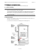
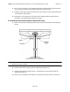
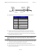
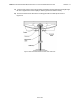
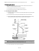
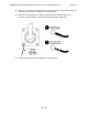
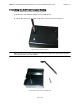
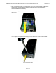
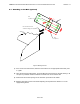
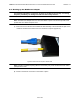
Table Of Contents

ABMAX CUSTOMER PREMISE EQUIPMENT INSTALLATION AND MAINTENANCE GUIDE VERSION 1.1
23
OF 42
Figure 6-3 Outdoor Transceiver End of the Interconnect Cable with Cable Preparation
5) Separate the twisted pair wires and align by color code in the order listed in Table 6-1.
Table 6-1 Cable Legend for Interconnect Cable
6) Using pin 1 as a reference, insert the individual wires into the channels of the RJ-45
connector. Each wire should penetrate the channels until flush with the connector end.
7) When all wires are inserted into the channels in their correct order, use the crimping tool to
permanently crimp the wires to the connector.
Attention! Carefully read the instructions for the crimping tool you are using. Use the
correct crimping tool for the RJ-45 connector you are using. Incorrect installation of the
RJ-45 connector may result in a bad connection between the outdoor transceiver and
wallbox.
8) Insert the RJ-45 connector into the receptacle located underneath the outdoor CPE. Make
sure that the connector tab engages the slot in the receptacle.
9) Slide the grommet up the cable and press it into the bottom of the outdoor CPE.
10) Slide the grommet clamp up the cable and align the holes with the mounting holes on the
bottom of the outdoor transceiver.
Pin Color Code
1 White / Orange
2 Orange
3 White / Green
4 Blue
5 White / Blue
6 Green
7 White / Brown
8 Brown