
Maintenance Guide
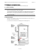
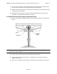
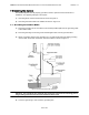
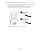
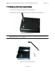
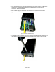
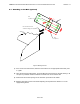
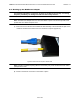
Table Of Contents

ABMAX CUSTOMER PREMISE EQUIPMENT INSTALLATION AND MAINTENANCE GUIDE VERSION 1.1
22
OF 42
2) Once you have chosen the route, determine the length of cable required. Allow three extra
feet on each end to allow for strain relief as well as any bends and turns.
3) Install the cable, leaving the ends free and ready to fit the RJ-45 connector (transceiver end),
and install to the indoor wallbox.
4) Remember to form a drip loop on the exterior of the building where the cable enters the
penetration. This will help prevent water from entering.
6.3 Install the Interconnect Cables (Transceiver End)
1) Remove the grommet and clamping plate from the outdoor transceiver by removing the two
screws.
Figure 6-2 Grommet Location - Underside of CPE
Note: The Grommet is made of a special conductive material used to complete the ground
between the CPE and wallbox.
2) Insert the cable end through the grommet clamping plate (Figure 6-2)
3) Insert the cable end through the grommet. The tapered end of the grommet should be
opposite the cable end.
4) Strip 1/2 inch of insulation off the cable end. Trim the wire ends flat as shown in Figure 6-3.