AB-MAX® Customer Premise Equipment Installation and Maintenance Guide Version 1.
Copyright 2006-2007 Axxcelera All rights reserved. Information Subject to Change without Notice Axxcelera reserves the absolute right to make changes to the information set forth in this Product Manual without notice. Specifications subject to change without notice. Customers may inquire as to whether they have the most current Product Manual by contacting Axxcelera Technical Support Department.
2. Redistributions in binary form must reproduce the above copyright notice, this list of conditions and the following disclaimer in the documentation and/or other materials provided with the distribution. 3. All advertising materials mentioning features or use of this software must display the following acknowledgement: “This product includes software developed by the OpenSSL Project for use in the OpenSSL Toolkit. (http://www.openssl.org/)” 4.
1. Redistributions of source code must retain the copyright notice, this list of conditions and the following disclaimer. 2. Redistributions in binary form must reproduce the above copyright notice, this list of conditions and the following disclaimer in the documentation and/or other materials provided with the distribution. 3.
TABLE OF CONTENTS 1 Preface ..................................................................................................................................................... 6 1.1 Who Should Read This Manual ...................................................................................................... 6 1.2 Conventions Used ........................................................................................................................... 6 1.3 Related Documentation ......................
ABMAX CUSTOMER PREMISE EQUIPMENT INSTALLATION AND MAINTENANCE GUIDE VERSION 1.1 1 Preface AB-MAX™ System technology enables high-speed, broadband Internet access for fast data transmission, full streaming video, real-time video conferencing, and web surfing. Axxcelera Broadband’s wireless point-to-multipoint (AB-MAX) solutions for fixed networks enables our customers to easily leap-over existing infrastructure, making the initial investment significantly lower than that required for wired alternatives.
ABMAX CUSTOMER PREMISE EQUIPMENT INSTALLATION AND MAINTENANCE GUIDE Telephone: Email: Web site: +1 (804) 864-4222 tech.support@axxcelera.com www.axxcelera.com 1.5 Sales You may contact the Sales Department for more information: Telephone: +1 (408) 894-0160 Fax: +1 (408) 894-9831 Email: Web site: sales@axxcelera.com www.axxcelera.com 7 OF 42 VERSION 1.
ABMAX CUSTOMER PREMISE EQUIPMENT INSTALLATION AND MAINTENANCE GUIDE VERSION 1.1 2 AB-MAX Product Overview 2.1 AB-MAX System The Axxcelera Broadband AB-MAX System is a broadband, fixed, wireless access network for Internet, data, video, and voice applications. AB-MAX can enhance or replace existing networks, wired or wireless, or be used to develop new networks. The AB-MAX System offers: • IEEE 802.16d / WiMAX air-link protocol (IEEE 802.
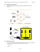
ABMAX CUSTOMER PREMISE EQUIPMENT INSTALLATION AND MAINTENANCE GUIDE VERSION 1.1 2.3.1 AB-MAX System Architecture Figure 2-1 and Figure 2-2 show an AB-MAX System’s typical deployment and network architecture. Figure 2-1 AB-MAX Typical Deployment Typically 6 Access Points per Base Station Base Station CPE Up to 500 CPEs per AP Access Point CPE Access Point Access Point Eth WAN NOC Router Eth Switch Figure 2-2 AB-MAX Typical Network Architecture 2.3.
ABMAX CUSTOMER PREMISE EQUIPMENT INSTALLATION AND MAINTENANCE GUIDE VERSION 1.1 • Termination Point and Lightning Arrestor • 48 VDC Power Supply • Uninterruptible Power Supply (UPS) (optional). 2.3.2.1 Access Points Figure 2-3 Outdoor Access Point and Mounting Pole A Base Station can have six Access Points (for 360-degree coverage) or more (for coverage overlap).
ABMAX CUSTOMER PREMISE EQUIPMENT INSTALLATION AND MAINTENANCE GUIDE VERSION 1.1 3 Pre-Installation 3.1 Compliance Alert The CE Marking with alert symbol (see below) appears on the Access Point assembly. The alert symbol indicates operation on frequency bands that are not harmonized throughout the European community. Figure 3-1 Compliance Alert Labe Note: This equipment operates in the 5 - 6 GHz frequency range, which is not harmonized throughout the community.
ABMAX CUSTOMER PREMISE EQUIPMENT INSTALLATION AND MAINTENANCE GUIDE VERSION 1.1 3.2.3 Protection from Lightning Article 810 of the US National Electric Department of Energy Handbook 1996 specifies that radio and television lead-in cables must have adequate surge protection at or near the point of entry to the building. The code specifies that any shielded cable from an external antenna must have the shield directly connected to a 10 AWG wire that connects to the building ground electrode. 3.2.
ABMAX CUSTOMER PREMISE EQUIPMENT INSTALLATION AND MAINTENANCE GUIDE 6) VERSION 1.1 Although you won’t wire an outlet, you will be required to run ground wires and clamp them to an earth grounding rod or a cold water pipe. If you can perform all the above tasks, then you should be able to install the AB-MAX System. If you are unsure of your ability to perform these tasks, contact a more qualified installer. 3.
ABMAX CUSTOMER PREMISE EQUIPMENT INSTALLATION AND MAINTENANCE GUIDE Tools Required VERSION 1.1 Extra Equipment Required Wire stripper Small wire cutters Punch down tool Table 3-1 Required Tools and Extra Equipment 3.6 CPE Packing List Table 3-2 lists all the standard parts (Figure 3-2) that are supplied in your AB-MAX Customer Premise Equipment Installation Package. Please take the time to unpack the CPE and check its contents against this list.
ABMAX CUSTOMER PREMISE EQUIPMENT INSTALLATION AND MAINTENANCE GUIDE VERSION 1.1 4 Installing the Mounting Poles First install the mounting poles, on which you will mount the outdoor transceivers. Bear in mind the direction in which the transceivers will point. Attention! The mounting pole must be mounted in a vertical position. Failure to do so may result in improper alignment of the outdoor transceiver.
ABMAX CUSTOMER PREMISE EQUIPMENT INSTALLATION AND MAINTENANCE GUIDE VERSION 1.1 Figure 4-3 Selecting an Access Point You should mount your outdoor Customer Premise Equipment as high as possible on your building, and align it to the compass reading you have just taken. For example, the previous Figure 4-3 shows the path to Access Point A obstructed by a cluster of trees.
ABMAX CUSTOMER PREMISE EQUIPMENT INSTALLATION AND MAINTENANCE GUIDE VERSION 1.1 Figure 4-4 Mounting Pole Installed on Pole or Antenna Mast 4.3 Installing On Brick or Masonry 1) Place the mounting plate against the wall (Figure 4-5). Use a level or plumb line to set the mounting pole perpendicular to the ground. 2) Mark the hole locations. 3) Set the pole aside. 4) Drill ¼ inch holes at the marked locations. Drill the holes approximately ½ inch deep.
ABMAX CUSTOMER PREMISE EQUIPMENT INSTALLATION AND MAINTENANCE GUIDE VERSION 1.1 4.4 Installing On a Wall with Wood Siding 1) Place the mounting plate against the wall. 2) Using a level, be sure that the mounting pole is perpendicular to the ground. You may need to use spacers, as shown in Figure 4-6. 3) Mark the hole locations for the drilled hole locations. Remove the mounting pole and set aside. 4) Drill 1/8-inch holes in the places marked.
ABMAX CUSTOMER PREMISE EQUIPMENT INSTALLATION AND MAINTENANCE GUIDE VERSION 1.1 5 Radio Installation 5.1 Before You Start This section lists the information needed to install a CPE. 5.2 Information Required Before you perform the installation, a site survey should have been performed by the service provider. From this, you will need to know: • Where the outdoor transceivers will be mounted (antenna mast, pole or building) • Heights at which the outdoor transceivers will be mounted.
ABMAX CUSTOMER PREMISE EQUIPMENT INSTALLATION AND MAINTENANCE GUIDE Figure 5-1 Outdoor Customer Premise Equipment Mounted on Wall 20 OF 42 VERSION 1.
ABMAX CUSTOMER PREMISE EQUIPMENT INSTALLATION AND MAINTENANCE GUIDE VERSION 1.1 6 Installing the Interconnect Cables For each interconnect cable, you will need to perform the following steps. 6.1 A Note On Cabling Attention! Most of the cabling used in the AB-MAX System is CAT5. You will need to be aware of the following limits on CAT5 cable lengths: 1. The interconnect cable from the indoor wallbox to an outdoor transceiver must be less than 100 meters.
ABMAX CUSTOMER PREMISE EQUIPMENT INSTALLATION AND MAINTENANCE GUIDE VERSION 1.1 2) Once you have chosen the route, determine the length of cable required. Allow three extra feet on each end to allow for strain relief as well as any bends and turns. 3) Install the cable, leaving the ends free and ready to fit the RJ-45 connector (transceiver end), and install to the indoor wallbox. 4) Remember to form a drip loop on the exterior of the building where the cable enters the penetration.
ABMAX CUSTOMER PREMISE EQUIPMENT INSTALLATION AND MAINTENANCE GUIDE VERSION 1.1 Figure 6-3 Outdoor Transceiver End of the Interconnect Cable with Cable Preparation 5) Separate the twisted pair wires and align by color code in the order listed in Table 6-1.
ABMAX CUSTOMER PREMISE EQUIPMENT INSTALLATION AND MAINTENANCE GUIDE VERSION 1.1 11) Insert the two screws in the mounting holes and tighten until the grommet has a slight bulge. Be sure to tighten both screws equally so that the grommet is seated correctly. 12) Secure the interconnect cable to the mounting pole with the cable clip as shown in Figure 6-4.
ABMAX CUSTOMER PREMISE EQUIPMENT INSTALLATION AND MAINTENANCE GUIDE VERSION 1.1 7 Grounding the System The AB-MAX System must be properly grounded in order to protect it and the structure it is installed on from lightning damage. This requires: 1) Grounding all the outdoor transceivers as shown in Figure 7-1. 2) Grounding the CAT5 cable to the wallbox as shown in Figure 7-2. 7.
ABMAX CUSTOMER PREMISE EQUIPMENT INSTALLATION AND MAINTENANCE GUIDE VERSION 1.1 5) Remove one of the lower mounting screws of the mounting pole. Insert a screw through the grounding lug terminal and re-install it to the mounting pole. 6) Attach the grounding wire to the clamp on the grounding rod, reference Figure 7-2. If necessary, use wire staples to secure the grounding wire to the outside wall.
ABMAX CUSTOMER PREMISE EQUIPMENT INSTALLATION AND MAINTENANCE GUIDE VERSION 1.1 8 Installing the NIA/Power Adapter Hookup Install the ABMAX CPE’s NIA/Power Adapter as follows: 1) Remove the new NIA/Power Adapter from the installation kit. 2) Flip the NIA over and use a Philips screw driver to remove the screw in Figure 8-1 Figure 8-1 Remove access cover screw Note: The NIA does not have a captive screw. Take care to retain this screw (Figure 8-2) when opening the access cover on the adapter.
ABMAX CUSTOMER PREMISE EQUIPMENT INSTALLATION AND MAINTENANCE GUIDE VERSION 1.1 3) Using a shielded RJ-45 plug, terminate (attach plug) to the outdoor CPE Cat-5 cable per the manufacturer's recommended specifications for plug attachment. (Recommended manufacturer: AMP P/N 5-569552). 4) Insert the RJ-45 plug from the outdoor CPE into the RJ-45 receptacle inside the NIA (Figure 8-3).
ABMAX CUSTOMER PREMISE EQUIPMENT INSTALLATION AND MAINTENANCE GUIDE VERSION 1.1 8.1 Attaching to the Wall (optional) Slot 2 places 5/ 9 NIA Pan Head screws for wall mounting (not supplied) Wall Slot 2 places Figure 8-5 Attaching to the wall 1) If the unit is to be wall mounted, mark two hole locations on an appropriate wall 23 mm (0.94 in.) apart. 2) Using the previously marked holes, screw two M4 pan head screws into the wall, leaving 3.18 mm (1/8 in.
ABMAX CUSTOMER PREMISE EQUIPMENT INSTALLATION AND MAINTENANCE GUIDE VERSION 1.1 8.2 Hooking up the NIA/Power Adapter It is extremely important to connect the AC power to the NIA as the last step. Connecting AC power prematurely can damage the CPE and lead to faulty behavior. Note: The NIA/Power Adapter does not come with cables or power cord. Service provider must provide their own cables and power cord.
ABMAX CUSTOMER PREMISE EQUIPMENT INSTALLATION AND MAINTENANCE GUIDE VERSION 1.1 3) Connect the two-wire power cord to the NIA. The power cord uses an IEC320-C7 type connector (Figure 8-7 and Figure 8-8) Then insert the power cord connector from the NIA into the nearest wall outlet. Figure 8-7 Connect the power cord Figure 8-8 Diagram of NIA’s IEC320-C7 type connector Note: It is extremely important to connect the AC power to the NIA as the last step.
ABMAX CUSTOMER PREMISE EQUIPMENT INSTALLATION AND MAINTENANCE GUIDE VERSION 1.1 4) The completed setup is shown in Figure 8-9. After verifying all connections to the NIA, connect the power cord to the wall and complete the process of setting up of the CPE.
ABMAX CUSTOMER PREMISE EQUIPMENT INSTALLATION AND MAINTENANCE GUIDE VERSION 1.1 9 Configuring the ABMAX CPE 9.1 Using the Online CPE Setup Screen Follow this procedure to configure the CPE using the CPE browser-based setup screens. 1) If the installer laptop is not running, power on and wait for the installer laptop to complete initialization to the desktop. 2) Set the PC IP address to be on the same network as the CPE. Note: Suggested to use config IP 10.1.1.2, netmask 255.255.255.0.
ABMAX CUSTOMER PREMISE EQUIPMENT INSTALLATION AND MAINTENANCE GUIDE VERSION 1.1 6) Add a channel by selecting the Duplex Mode from a dropdown list and entering the Channel Bandwidth and Downlink Frequency in their corresponding fields. Click Add, and the new channel will appear in the Channel List.
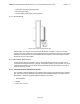
ABMAX CUSTOMER PREMISE EQUIPMENT INSTALLATION AND MAINTENANCE GUIDE VERSION 1.1 7) To scan channels in the list, select the channels that you wish to scan by clicking the checkboxes (Figure 9-2) to the left of the Operator ID column. 8) Click Scan.
ABMAX CUSTOMER PREMISE EQUIPMENT INSTALLATION AND MAINTENANCE GUIDE VERSION 1.1 9) When the scanning is complete, the Scan Result(s) screen appears (Figure 9-3). It displays the channels that you selected. If a signal is found, the radio button will be available for selection. If no signal was found for a channel, its radio button will be grayed out. 10) Click the radio button of the desired signal.
ABMAX CUSTOMER PREMISE EQUIPMENT INSTALLATION AND MAINTENANCE GUIDE VERSION 1.1 12) The Connection Result screen displays a summary of the results. Figure 9-4 Connection Result screen 13) Once you have successfully connected the CPE to a channel, you can close your browser.
ABMAX CUSTOMER PREMISE EQUIPMENT INSTALLATION AND MAINTENANCE GUIDE VERSION 1.1 Appendix A: Glossary of Terms and Abbreviations A.1 Terms and Definitions Term Definition Access Point An Access Point (AP) is a component of a Base Station (BS) that contains the antenna used to communicate with a Customer Premise Equipment (CPE). Antenna A device for transmitting and/or receiving radio waves.
ABMAX CUSTOMER PREMISE EQUIPMENT INSTALLATION AND MAINTENANCE GUIDE Term VERSION 1.1 Definition Packet Switching Packet switching is the data transmission method that divides messages into standard-sized packets for greater efficiency of routing and transport through a network. Parsing Parsing is the process of analyzing a data stream and breaking it down into more easily processed components. Point-to-Point A single communication circuit connecting two locations.
ABMAX CUSTOMER PREMISE EQUIPMENT INSTALLATION AND MAINTENANCE GUIDE VERSION 1.1 A.2 Acronyms/Abbreviations The following is a list of acronyms and abbreviations associated with the AB-MAX System, some of which may appear in this guide.
ABMAX CUSTOMER PREMISE EQUIPMENT INSTALLATION AND MAINTENANCE GUIDE Acronym Definition PTMP Point to Multipoint QOS Quality of Service RF Radio Frequency RSSI Receiver Signal Strength Indication SNMP Simple Network Management Protocol SNR Signal to Noise Ratio TCP/IP Transmission Control Protocol/Internet Protocol TDD Time Division Duplex TDMA Time Division Multiple Access 41 OF 42 VERSION 1.
ABMAX CUSTOMER PREMISE EQUIPMENT INSTALLATION AND MAINTENANCE GUIDE Index R Radio Installation 19 Before You Start 19 Information Required 19 Installing the Equipment 19 Installing the Outdoor Customer Premise Equipment 19 A AB-MAX Product Overview 8 System 8 System Architecture 9 System Components 8 Topology 8 AC power 31 Access Points 10 Arcing 11 S Safety Precautions 11 FCC Notice, USA 12 Protection from Lightning 12 Selecting an Access Point 15 Site Survey What You Need 15 System Components Access