
Installation Manual Part 2

Company Proprietary
Adaptive Broadband
U-NII Product Installation Manual 05/29/2001
7-8
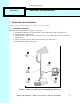
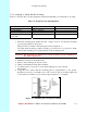
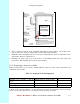
Figure 7-8 Interconnect Cable Routing Solutions
2. Once you have chosen the route, determine the length of cable required. Allow three extra
feet on each end to allow for strain relief as well as any bends and turns.
3. Install the cable, leaving the ends free and ready to fit the RJ-45 connector (transceiver end),
and install to the indoor junction box.
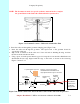
4. Remember to form a drip loop on the exterior of the building where the cable enters the
penetration. This will help prevent water from entering.
7.5.2 Preparing the Interconnect Cable
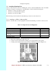
Table 7-6 shows the tools you need to install an RJ-45 connector on the outdoor subscriber end
of the interconnect cable.
Table 7-6 Required Tools and Equipment
Tools Equipment Quantity
Crimping tool (specific to RJ-45
used)
RJ-45 connector (metal bodied) 1
Wire stripper
Small wire cutters
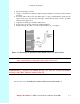
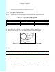
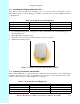
1. Remove the grommet (Figure 7-9) and clamping plate from the Subscriber Unit by undoing
the two screws. Be careful not to lose them if you are working on a ladder.
NOTE - Add a
drip loop at wall
penetration
to
prevent water
from entering