
Installation Manual Part 2

Company Proprietary
Adaptive Broadband
U-NII Product Installation Manual 05/29/2001
10-4
TBD: Insert AB-Access Extender Antenna Pattern image
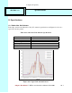
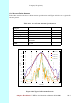
Figure 10-3 Typical EX Antenna Pattern
TBD: Update all section and figure numbers from here on forward
10.4 Modem Specifications
The QPSK modem design for the transceiver is driven primarily by the 32-symbol correlator and
Decision Feedback Equalizer (DFE). The correlator output is used for:
• Burst detection
• Digital AGC setting
• Phase reference
• AFC control
• Course symbol timing.
The DFE is used to remove the Inter-Symbol Interference (ISI) introduced by the filters and
imperfect sampling, as well as compensate for pre-cursor and post-cursor channel multipath.
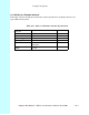
Table 10.4 shows the Modem Specifications.
Table 10-4 Modem Specifications
Modulation Coherent QPSK
Symbol rate 12.5 Msym/s
ADC 10 bits I and Q
Receive filter Root raised cosine =0.35
AWGN performance 14.4 dB CNR for 10
-4
BER (including 3 dB
implementation loss)
Equalizer Decision Feedback (DFE); 5 forward taps, 4
feedback taps; delay spreads up to 0.32 s;
post cursor to cursor ratios up to 0.5
Training 32 symbols per burst
Transmit filter Raised cosine =0.35
10.5 Environmental Specifications
10.5.1 Temperature/Humidity Operation
The entire unit is constructed in a weatherproof housing and designed for outdoor use. The
minimum and maximum operating temperatures and the relative humidity for all system
elements are listed in Table 10.5.