
Installation Manual Part 2

Company Proprietary
Adaptive Broadband
U-NII Product Installation Manual 05/29/2001
7-12
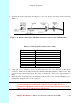
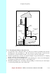
2. Insert the cable end through the notched out section of the junction box.
3. Reinstall the PCB into the junction box using the two screws, allowing enough of the
interconnect cable to be able to reach the punch down block and wrap around the mounts of
the cover plate for strain relief.
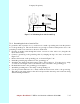
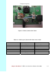
4. Using Figure 7-13 as a guide, use the 110 punch down tool to punch down each wire into the
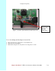
slot on the punch down block (reference the following Figure 6-16 which shows the inside of
the Junction Box).
Figure 7-13 Interconnect Cable Connections to Indoor Junction Box
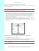
5. Snip off excess wire ends, if necessary.
Attention! Avoid excessive wire loops when connecting the wire to the punch down block.
For now, set the junction box to one side leaving it disassembled. You will reassemble it and
mount it on the wall when you have grounded the system.
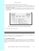
7.6 Grounding The System
The AB-Access System must be properly grounded in order to protect it and the building it is
installed on from lightning damage. This requires grounding both the outdoor transceiver and
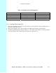
indoor junction box. The following Table 7-8 describes the tools you will need to ground the
system.